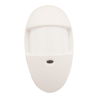
AURORA / AURORA-T
Passive Infrared Motion Detectors
INSTALLATION INSTRUCTIONS
GENERAL INFORMATION
These passive infrared motion detectors are versatile wall-mounted
units employing Fresnel lenses and offering efficient protection
patterns for commercial and residential applications. Best coverage
will be obtained if mounting is selected such that the likely direction of
intruder motion is across the pattern.
When installed per the guidelines, the Split-Zone Optics technology in
the Aurora Series provides reasonable false alarm protection against
pets and other animals up to 40 lbs.
SPECIFICATIONS
Detection Method: Passive Infrared
Coverage: Pet Immune Lens,
35 ft x 45 ft (10.6m x 13.7m), 90°
Detection Zones: Pet Immune Lens - 28 zones
(8 over 8 long range, 8 intermed, 4 short range)
Pulse Processing: Intermediate, Standard, Harsh
(use “Standard” for pet immune applications)
Temperature Comp.: Advanced dual-slope temperature
compensation adjusts for ambients both
above and below body temperature
Detectable Walk Rate: 0.5 - 10 ft/Sec (0.15 - 3m/Sec)
Mount Height: 7.0 ft recommended (2.1m)
Indicator: Red LED with enable/disable link
Alarm Relay: Form A, SPST, 90mA@16VDC,
15-ohm protective resistor
Input Voltage: 8 - 16VDC (Aurora and Aurora-T)
(voltage reversal makes PIR inoperative)
Current: Model w/LED alarm w/o LED standby
Aurora 10mA 4mA 4mA
Aurora-T 10mA 4mA 4mA
All currents nominal at 12VDC.
Standby: Power source should be capable of at least 4
hours of battery standby
Tamper: Normally closed (with cover on), rated at 0.5A,
30VDC (Aurora-T only)
Operating Temp.: 14°F - 122°F (-10°C to +50°C)
Operating Humidity: Up to 95% RH (max.), non-condensing
Dimensions: 2.9”W x 4.1”H x 1.5”D (max protrusion)
(60mm x 104mm x 38mm)
Approvals/Listing: UL639, ULC S306,
EN 50131-1; Security Grade 2, Environment
Class II
For Connection to an EN 60950 Class II
Limited Power Source
(2) REMOVE
COVER
LED
(1) INSERT
SCREWDRIVER
IN GROOVE
AND TWIST
PLACE LEVEL AGAINST
THESE POINTS TO ENSURE
UNIT IS VERTICAL.
AURORA-002
Figure 2. Cover Removal
X1
A
B
B
A
X2
TOP
LED
ENABLE/DISABLE
JUMPER LINK
PULSE
PROCESSING
SELECTION
JUMPER LINK
AURORA-004
Figure 3. Detector Base
0
22.5'
22.5'
10'
20'
30'
35'
0
7'
0
10'
20'
30'
35'
SIDE VIEW
TOP VIEW
ALTERNATE COUNT POLARITY
EACH ZONE CONSISTS OF 2 FIELDS
0
10 20 30 40 50 60 70 75
5
0
5
0
10 20 30 40 50 60 70 75
0
5
10
SIDE VIEW
TOP VIEW
INSTALLATION
For optimal pet immunity performance, be sure to follow all the guidelines
described in “Special Instructions for Installations Containing Pets.”
A. Normal Surface Mounting
Mount the unit to a firm vertical surface. The wall wiring hole should be no
more than 5/16” (8mm) in diameter.
1. Remove the front cover as shown in Figure 2.
2. Refer to Figure 3. Knockout holes “A” in the base are for normal surface
mounting on a wall (remove PC board for full access to holes). For
corner mounting, see B. Corner Mounting. Also break out the desired
wire entry hole at this time, marked X1 or X2 in Figure 3.
3. Feed wiring through the wire access hole. Make sure wires have
sufficient slack to allow the PC board to be moved up and down freely
when the wires are connected to the board’s terminals.
4. Mount the base. A level may be used on the front case to ensure that
the unit is vertical (see Figure 2).
5. Replace the PC board, positioning it to the appropriate setting (see
Vertical Lens Adjustment table later in this document). Note the
mounting orientation of this detector: terminal strip at the bottom!
6. Refer to the WIRING CONNECTIONS section before replacing the front
cover.
B. Corner Mounting
1. Remove the front cover as shown in Figure 2.
2. Knockout holes “B” in the base are used for corner mounting on a wall.
Mount in selected corner with 4 screws.
3. Replace the PC board, positioning it to the appropriate setting (see
Vertical Lens Adjustment table later in this document). Note the
mounting orientation of this detector: terminal strip at the bottom!
4. Refer to the WIRING CONNECTIONS section before replacing the front
cover.
Special Instructions for Installations Containing Pets
To take full advantage of the pet immunity in the Aurora Series, the
guidelines below should be followed:
• Mount the center of the detector 7 ft (2.1m) high.
• Set the PIR sensitivity for Standard (STD).
• Mount where animals cannot come within six feet of the detector by
climbing on furniture, boxes, or other objects.
• Do not aim the detector at stairways that can be climbed by animals.
NOTE: This unit will provide immunity to false alarms for an individual
animal or a group of animals whose total weight is equal to or less than 40
lbs when the room temperature is above 50°F (10°C).