Do you have a question about the Honeywell CHRONOTHERM III T8611G and is the answer not in the manual?
| Power Source | 24 VAC |
|---|---|
| Display Type | LCD |
| Program Schedule | 7-day programmable |
| Programmability | Yes |
| Power Method | Hardwired |
| Operating Voltage | 20-30 VAC |
| Voltage | 24 VAC |
| Backlight | No |
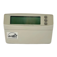
| Type | Programmable Thermostat |
| Compatibility | Gas, oil, electric systems |
| Stages | 1 Heat/1 Cool |
| Terminal Designations | R, W, Y, G |
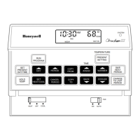
Describes thermostats for 24 Vac multistage heat pump systems with 5-1-1 programming and LED indicators.
Details the function of SYSTEM, ENRG SAV, AUX. HT., EM. HT., and CHECK LEDs on the thermostat and subbase.
Includes warnings about power disconnection, wire handling, and proper installation environment.
Install thermostat 5 ft. above floor in area with good air circulation, avoiding drafts and heat sources.
Covers replacing existing thermostats, new installations, mounting subbases, and wiring requirements.
Comply with electrical codes, disconnect power, and use appropriate wiring connections.
Adjusts thermostat cycling performance for heating equipment for optimum savings.
Install three AAA batteries for program backup in case of power outage.
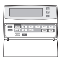
Hang thermostat on subbase tabs, press into place, and tighten captive mounting screws.
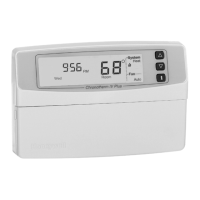
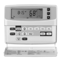
Set the present day and time after restoring 24V power to the thermostat.
Describes setting temperatures for heating and cooling modes, including compressor delays.
Explains continuous fan operation and fan cycling with heating or cooling systems.
Perform a test of all thermostat functions by pressing specific key combinations.
Explains the meaning of the four digits displayed during the self-test diagnostic mode.