MERLIN NX ROOM CONTROLLER – INSTALLATION & COMMISSIONING INSTRUCTIONS
11 EN1Z-1035GE51 R0420
POWER SUPPLY
General Information
CAUTION
To prevent a risk of injury due to electrical shock
and/or damage to device due to short-circuiting, low-
voltage and high-voltage lines must be kept physically
separate from one another.
Further, to prevent a risk of short-circuiting and
damage to your unit, do not reverse the polarity of the
power connection cables, and avoid ground loops
(i.e., avoid connecting one field device to several
controllers).
NOTE: All wiring must comply with applicable electrical
codes and ordinances. Refer to job or manu-
facturers’ drawings for details. Local wiring guide-
lines (e.g., IEC 364-6-61 or VDE 0100) may take
precedence over recommendations provided in
these installation instructions.
NOTE: To comply with CE requirements, devices having a
voltage of 50...1000 VAC or 75...1500 Vdc but
lacking a supply cord, plug, or other means for
disconnecting from the power supply must have the
means of disconnection (with a contact separation of
at least 3 mm at all poles) incorporated in the fixed
wiring.
Wiring
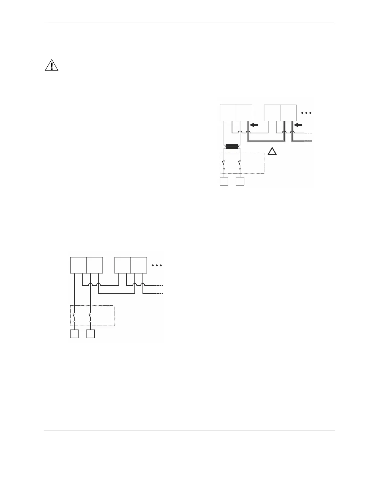
230-VAC Models
The 230-VAC models are powered via an orange fixed screw-
type terminal block (terminals 1+2). See also Fig. 16. These
terminals support 1 x 4 mm
2
or 2 x 2.5 mm
2
wiring.
230 VAC
(-15% / +10%),
50 / 60 Hz
1
L
1
L
NL
2
N
2
N
230-VAC MODEL #1 230-VAC MODEL #2
Fig. 16. Multiple 230-VAC models connected to single
power supply
24-VAC Terminals for Auxiliary or Field Devices
All 24-VAC auxiliary power supply terminals support 1 x 2.5
mm
2
or 2 x 1.5 mm
2
wiring.
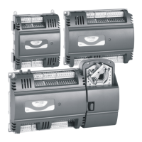
24-VAC Models
The 24-VAC models are powered via a black removable
terminal plug (terminals 3+4), thus allowing daisy chain wiring
of the power supply. See also Fig. 17. These terminals
support 1 x 2.5 mm
2
or 2 x 1.5 mm
2
wiring.
120 VAC
or
230 VAC
(-15% / +10%),
50 / 60 Hz
24 VAC
(+/-20%)
3
24V~
3
24V~
NL
4
24V0
4
24V0
24-VAC MODEL #1 24-VAC MODEL #2
CAUTION
ALWAYS CONNECT TERM. 4
(24VAC0) OF EVERY 24-VAC
MODEL TO TERM.
.
FAILURE TO COMPLY WILL
RESULT IN SHORT-CIRCUITING!
4 (24VAC0)
OF EVERY OTHER 24-VAC
MODEL
!
Fig. 17. Multiple 24-VAC models connected to single
power supply
Communication / Signal Terminals
All other (i.e.: communication / signal) terminals (except for
the Sylk Bus – see Table 11) support 1 x 2.5 mm
2
or 2 x 1.5
mm
2
wiring. Two wires with a total thickness of 2.5 mm
2
(14 AWG) can be twisted together and connected using a
wire nut (include a pigtail with this wire group and attach the
pigtail to the individual terminal block). Deviations from this
rule can result in improper electrical contact. Local wiring
codes may take precedence over this recommendation.
 Loading...