MERLIN NX ROOM CONTROLLER – INSTALLATION & COMMISSIONING INSTRUCTIONS
19 EN1Z-1035GE51 R0420
▪ Must conform to TIA/EIA-485 cabling guidelines and
ANSI/ASHRAE Standard 135-2010.
▪ There are two limitations regarding the number of
controllers per BACnet MS/TP channel:
- 1. Physical limitation:
32 loads as per TIA/EIA-485 standard. One MERLIN
NX controller represents ¼ load. The physical
limitation is important in case 3
rd
party devices
representing a full load are connected.
- 2. AutoMAC limitation:
We have tested with a maximum of 64 for maxMaster.
A maxMaster of 64 means we support a maximum of
62 MERLIN NX controllers, one supervisor, and one
BACnet client (tool) per BACnet MS/TP channel.
The default value for maxMaster is 35, as this is the
maximum supported by some plant controllers.
In the event that you have a plant controller capable of
supporting more than 35 devices, it will therefore be
necessary for you to increase the maxMaster setting
to the actual required number of devices (e.g., to the
maximum number of 64). Refer to the Niagara IRM
Engineering Tool – User Guide (EN2B-0414GE51) for
more information on how to do this.
Thus, depending upon your actual performance needs
and required communication rates, we recommend con-
necting less than the maximum number of BACnet MS/TP
devices per channel.
END
END
BIAS
MID
CPO-RSxN CPO-RLxN
BACnet MS/TP
DEVICE #1
(MASTER)
BACnet MS/TP
DEVICE #2
(SLAVE)
BACnet MS/TP
DEVICE #N-1
(SLAVE)
BACnet MS/TP
DEVICE #N
(SLAVE)
120Ω
GND
RS485 -
RS485 +
C1+
C1+
C1-
C1-
GND
GND
EAGLE /
EAGLEHAWK NX
PLANT CONTROLLER
Excel Web II /
24
25 26 40
41 42
62 63 64
L
TWISTED
PAI R
NOTE 1
GENERIC
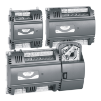
Fig. 24. Connection to a BACnet MS/TP Bus
With regards to Fig. 24, please refer to the following NOTES.
NOTE 1: If any of the devices are electrically isolated, it is
recommended that those devices be connected to
the ground terminal (GND), if available. See section
"The TIA/EIA-485 Standard" on pg. 18.
NOTE 2: 120-Ohm termination resistors must be inserted
directly into the terminals of both end devices. (In the
case of the EAGLE / Excel Web II / EAGLEHAWK
NX / CPNX Plant Controller, this is instead
accomplished by setting the three-position slide
switch to "END" and inserting a resistor only into the
terminals of the device at the other end.)
NOTE 3: If shielding is used, the shielding of each individual
bus segment should be separately connected at one
end to earth.
NOTE 4: Always power each controller and the connected
slaves via separate transformers.
NOTE 5: Between devices equipped with non-isolated RS485
bus interfaces, potential differences of max. ±7 V are
allowed. Further, this bus should not extend beyond
a single building.
For details, refer to the respective Installation Instructions
listed in section "Related Technical Literature" on pg. 27.
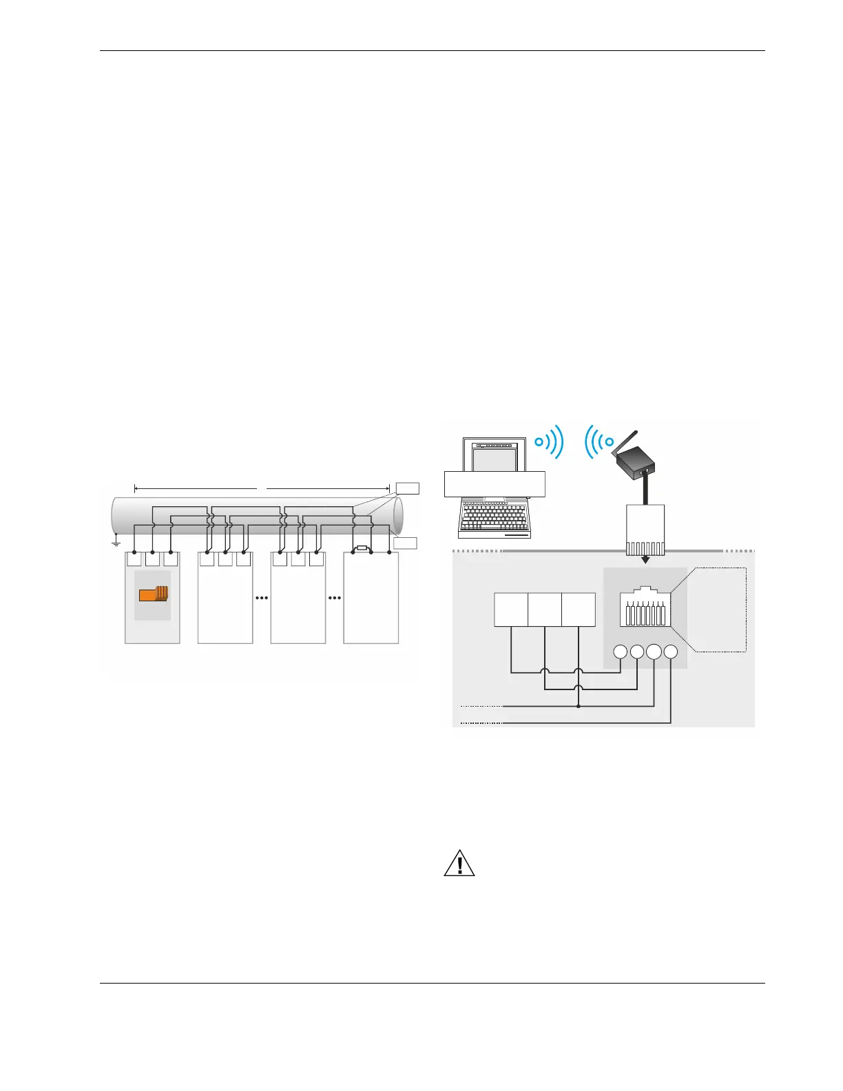
RJ45 Connector for BACnet WiFi Adapter
A BACnet WiFi Adapter can be connected to the controller's
RJ45 connector in order to establish wireless communication
with a PC with COACH NX so that the application engineer
can commission the controller.
NOTE: When the BACnet WiFi Adapter is connected to the
controller's RJ45 connection, it is powered by the
controller. It is then prohibited to simultaneously
power the BACnet WiFi Adapter via a wall adapter.
When, on the other hand, the BACnet WiFi Adapter
is instead connected to the controller's BACnet
MS/TP interface, it is prohibited to simultaneously
use an RJ45 plug; instead, the BACnet WiFi Adapter
must then be powered by a wall adapter (standard
5-V USB wall adapter with micro USB connector).
See also corresponding Technical Literature listed in Table 13
on pg. 27.
CLMERLxN
(CLMERSxN)
8 7 6
5
4 3 2 1
7 8
4
2,3,
5,6
RJ45 CONNECTOR
INTERNAL
CONNECTIONS
BACnet MS/TP
62
(40)
C1+
63
(41)
C1-
64
(42)
GND
1 = DETECT
2 = GND
3 = GND
4 = 24VAC
5 = GND
6 = GND
7 = C1+
8 = C1-
COACH NX
BACnet WiFi
ADAPTER
RJ45
PLUG
Fig. 25. RJ45 interface and BACnet WiFi Adapter
NOTE: When the BACnet WiFi Adapter is used to com-
mission the controller, the property maxMaster must
be set to its default value of 35 or lower; this is be-
cause the BACnet WiFi Adapter supports a maxi-
mum of 35 BACnet MS/TP-capable devices.
CAUTION
It is permitted to connect only the BACnet WiFi
Adapter to this RJ45 connector. Do not connect IP!
 Loading...