CPO-PC400-W/CPO-PC400-UW HVAC CONTROLLER
29 EN0B-0085 IE10 R0420
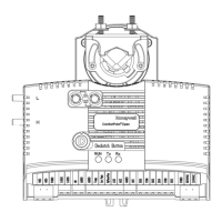
Connection to Modbus devices with non-isolated RS485 interfaces
Fig. 20. Connection (L > 3 m) of RS485 interfaces 1, 2, or 3 (RS485 interface 1 shown) to a Modbus
NOTES:
— N = max. 30 unit loads. Always power the CPO-PC400-W/CPO-PC400-UW and connected Modbus modules
with separate transformers. Termination resistors must be inserted directly into the terminals of the individual
Modbus modules.
— Signal ground (signal reference) connection is recommended. For more information, see “General Information
on the RS485 Standard” section on page 7.
— For communication cable lengths, transmission speeds, and termination, see “General Information on the
RS485 Standard” section on page 7. For fusing, see “Fusing” section on page 11.
TX
5V
GND
Modbus
Module #1
Isolaon
Barrier
RX
5V_ISO
GND_ISO
RS485+
RS485-
RT
110VAC/230VAC
24VAC
Modbus
Module #N
F1
RS485+
RS485-
Common
L > 3m
RT
RS485+
RS485-
Common
FGND
24V0
24V~
CH1+
CH1-
GND1
CPO-PC400-W/CPO-PC400-UW
 Loading...