CX Series
ISSUE 4 PK 88136
SETUP INSTRUCTIONS FOR UNITS WITH 2-WIRE ANALOG (4 TO 20 mA) OUTPUT
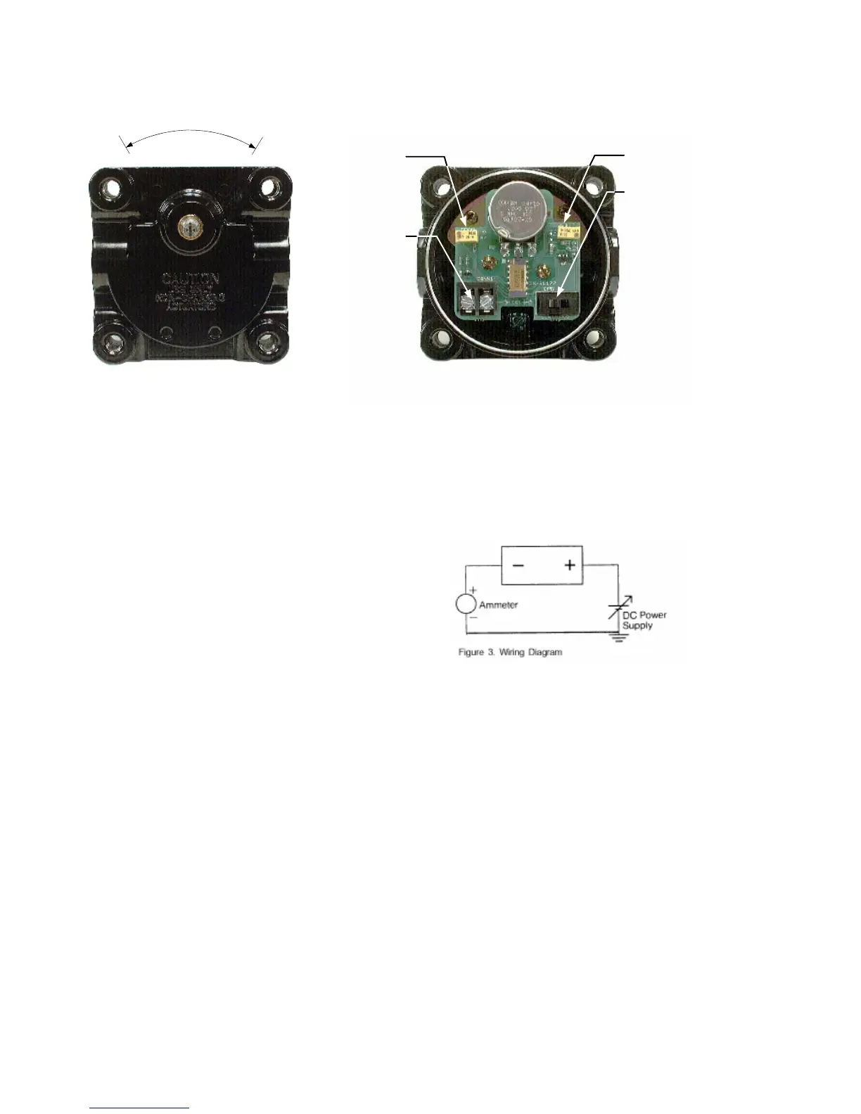
CCW CW
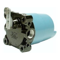
Figure 1. Shaft End View
Function Switch
Right position:
Output increases
with clockwise
rotation of shaft
(viewed from front)
Left position: Output
increases with
counterclockwise
rotation of shaft
(viewed from front)
Null Trimmer
Potentiometer
Span Trimmer
Potentiometer
Output
Terminals
Figure 2. Rear View with Cover Removed
Procedure 1
1. Determine the position of the operating shaft as
it relates to the valve and actuator (where the 4
mA output is required).
2. Remove cover and set the function switch to
enable the output to be increased by
counterclockwise (CCW) or clockwise (CW)
motion of the shaft. Refer to figures 1 and 2.
Procedure 2
Reposition the shaft by using either Step 1 or 2,
below.
Use step 1 if the function switch is set in the CW
position.
1. Rotate operating shaft a quarter turn (90°) CCW
and then a quarter turn CW (back to initial
position).
Next, rotate shaft a half (180°) turn CW and then
a half turn CCW (back to initial position.)
Use Step 2 if the function switch is set in the CCW
position.
2. Rotate operating shaft a quarter turn (90°) CW
and then a quarter turn CCW (back to the initial
position).
Next, rotate shaft a half turn (180°) CCW and
then a half turn CW (back to initial position).
Procedure 3
1. Wiring (See figure 3). Connect a 12.5 to 40 VDC
(nominal) power supply to the positive (+)
terminal. Connect an ammeter to the negative (-)
terminal.
2. Set shaft to position where 4 mA output is
desired.
3. Adjust the null offset trimmer potentiometer (see
figure 2) to generate 4 mA at this position.
(Clockwise turn increases the output.)
4. Rotate shaft to position where 20 mA output is
desired.
5. Adjust the span trimmer potentiometer (see
figure 2) until output is 20 mA. (Clockwise turn
increases output.)
6. Return shaft to initial position and check for 4
mA. Adjust offset null trimmer if necessary.
7. Return shaft to final position and check for 20
mA. Adjust span trimmer if necessary.
NOTE: Honeywell recommends repeating
Procedure 3 after 50,000 operations.
4 Honeywell • Sensing and Control
 Loading...