33-00135EFS—07 10
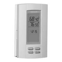
When the ERM is connected to the system, the ERM’s “Connected” LED will be
solid green and the thermostat will show “ERM” in its Wireless Manager. (Fig.
10)
Fig. 10.
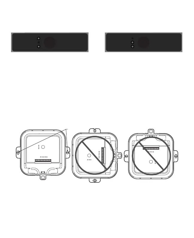
Mounting ERM
9. Use two screws and wall anchors to attach the ERM to the exte-
rior wall near the compressor. The location should be at least
3 feet above ground and oriented with the two wire exits fac-
ing downward. See Figs. 11 and 12.
10. Attach cover and secure with bottom screw (Fig. 13).
Fig. 11. Mounting orientation.
MCR35661
CONNECTED LED STATUS
Connect
Flashing: Device Connecting
Green: Device Connected
Red: Not Communicating
Compressor
Boiler
Connected
MCR35662
CONNECTED LED STATUS
Connect
Flashing: Device Connecting
Green: Device Connected
Red: Not Communicating
Compressor
Boiler
Connected
MCR35665
MOUNTING
SCREWS
CORRECT
Equipment Remote Module I ERM5000R
Compressor
Boiler
Connected
Connect
CONNECTED LED STATUS
Flashing: Device Connecting
Green: Device Connected
Red: Not Communicating
Compressor:
Jump J and R
Boiler:
Remove Jumper
J
R
C
Y1
Y2
T
O/B
T
D
L
S1
S1
INCORRECTINCORRECT
Equipment Remote Module I ERM5000R
Compressor
Boiler
Connected
Connect
CONNECTED LED STATUS
Flashing: Device Connecting
Green: Device Connected
Red: Not Communicating
Compressor:
Jump J and R
Boiler:
Remove Jumper
J
R
C
Y1
Y2
T
O/B
T
D
L
S1
S1
Equipment Remote Module I ERM5000R
Compressor
Boiler
Connected
Connect
CONNECTED LED STATUS
Flashing: Device Connecting
Green: Device Connected
Red: Not Communicating
Compressor:
Jump J and R
Boiler:
Remove Jumper
J
R
C
Y1
Y2
T
O/B
T
D
L
S1
S1
33-00135EFS_D.book Page 10 Friday, September 8, 2017 1:59 PM
 Loading...