DISTRIBUTED I/O
EN0B-0090GE51 R0802 22
in a different cabinet, or allow a minimum distance of
18 inches (50 cm) between frequency converters
and their respective cabling, and Distributed I/0
Modules.
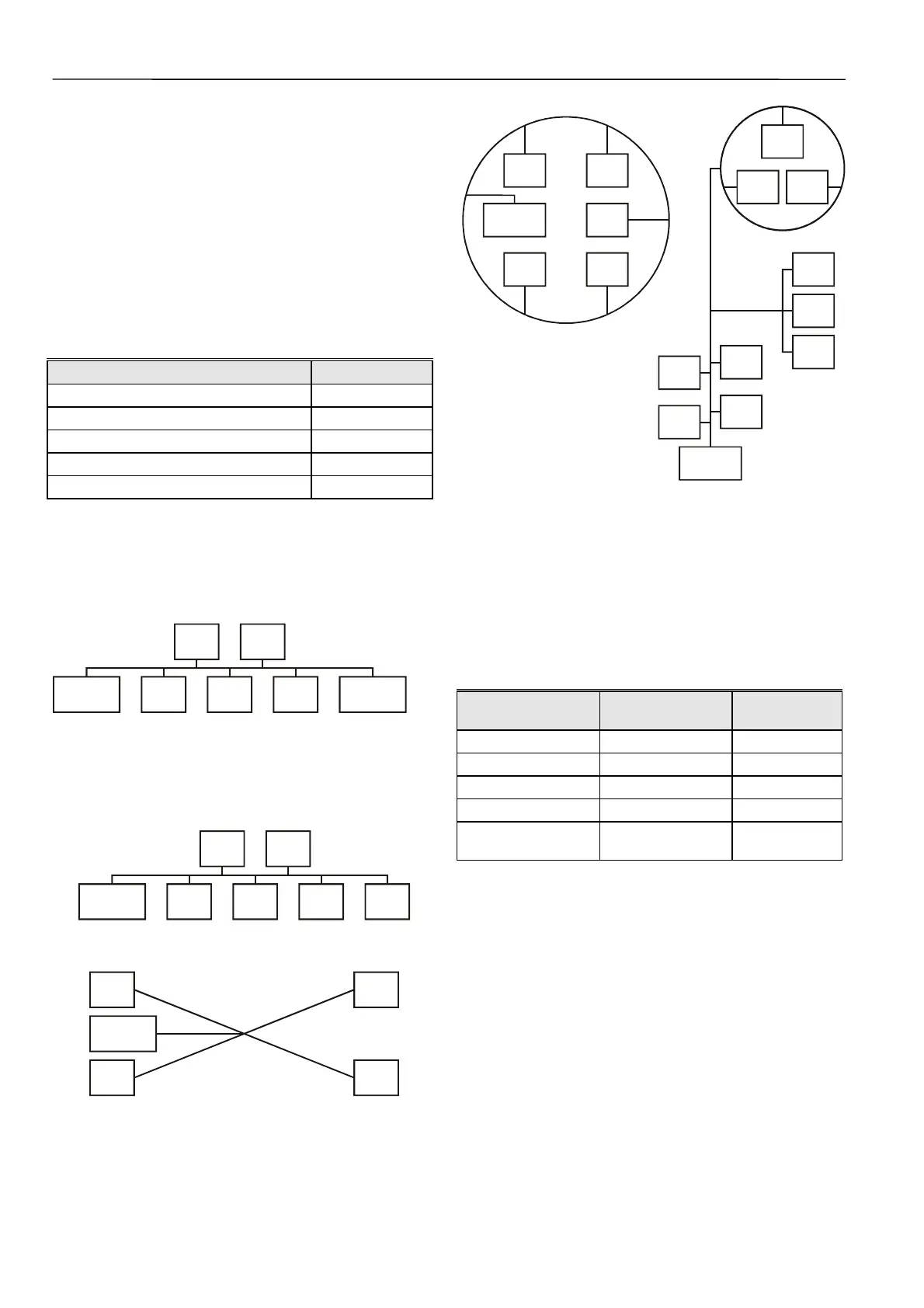
FTT devices can be wired in daisy chain, star, loop or any
combination thereof as long as the maximum wire length re-
quirements given below are met. The recommended con-
figuration is a daisy chain with two bus terminations. This
layout allows for maximum bus length, and its simple struc-
ture presents the least number of possible problems, par-
ticularly when adding on to an existing bus.
NOTE: A doubly-terminated bus may have stubs of up to
10 ft (3 m) from the bus to each node.
Table 13. Doubly-terminated bus specifications
Cable type Max. bus length
Belden 85102 8,900 ft (2,700m)
Belden 8471 8,900 ft (2,700m)
Level IV, 22 AWG 4,600 ft (1,400m)
JY (St) Y 2x2x0.8 3,000 ft (900m)
TIA568A Categ. 5 24AWG, twisted pair 3,000 ft (900m)
NOTE: The cable types listed above are as recommended
by Echelon® in their FTT-10A User Guide. The
cable recommended by Honeywell is the level IV, 22
AWG, solid core, non-shielded cable. Belden part
numbers are 9H2201504 (plenum) and 9D220150
(non-plenum).
termination
module
termination
module
device
device device
device device
Fig. 29. Doubly-terminated bus configuration
(recommended)
Free topology requires only one bus termination and allows a
variety of bus configurations (see Fig. 30):
termination
module
device
device device
device device device
singly-terminated
device
device device
device
star
termination
module
Fig. 30. Possible bus configurations
device
device
device
device
device
termination
module
termination
module
device
device
device
device
device
device
device
device
device
device
loop
mix
Fig. 31. Free topology examples
The FTT specification includes two components that must be
met for proper system operation. The distance from each
transceiver to all other transceivers and to the termination
must not exceed the maximum node-to-node distance. If
multiple paths exist, the maximum total wire length is the total
amount of wire used.
Table 14. Free topology (singly-terminated)
specifications
Cable type
Maximum node-
to-node distance
Maximum total
wire length
Belden 85102 1,650 ft (500 m) 1,650 ft (500 m)
Belden 8471 1,300 ft (400 m) 1,650 ft (500 m)
Level IV, 22AWG 1,300 ft (400 m) 1,650 ft (500 m)
JY (St) Y 2x2x0.8 1,050 ft (320 m) 1,650 ft (500 m)
TIA568A Category 5
24AWG, twisted pair
825 ft (250 m) 1,500 ft (450 m)
IMPORTANT
Do not use different wire types or gauges on the
same L
ONWORKS network segment. The step
change in line impedance characteristics would
cause unpredictable reflections on the bus.
Examples of allowed and not-allowed free topology layouts
for cable JY (St) Y 2x2x0.8 are shown in Fig. 32.

 Loading...


