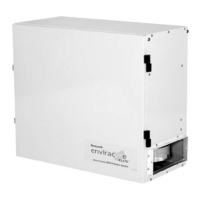
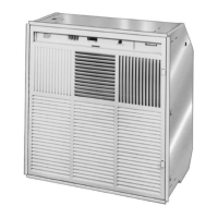
F57A,B FLUSH-MOUNT COMMERCIAL ELECTRONIC AIR CLEANER
68-0083-7 Revised 11-07
10
KNOCKOUT KNOCKOUT
FIELD SUPPLIED
DAMPER
M7640
Air Vent
The air vent helps to control gaseous contaminants such as
by-products of cigarette smoking by allowing some of the air
circulated through the F57 to be discharged into the return
plenum.
To use the air vent, remove the five inch knockout in the side
of the F57 cabinet. See Fig. 7. When venting into the false
ceiling cavity, leave the vent fully open. When ducting into the
return plenum, install damper and position it to reduce the
opening by 50 percent.
Fig. 7. Air vent adjustment.
Wiring
IMPORTANT
Before wiring the F57, remove the power supply
cover. After completing the wiring procedures,
reattach the power supply cover.
All wiring must comply with applicable codes and ordinances.
The power source to the F57A,B must agree with the model
type, either 120 Vac, 60 Hz or 220–240 Vac, 50 Hz.
To wire 120 Vac, 60 Hz model:
• Run three No. 14 color-coded wires through the conduit to
the wiring compartment of the F57. Attach the green wire
to the external ground. The black and white wires are the
power carriers.
• Attach the conduit to the knockout desired (either the
large or small knockout).
• Attach the green ground wire to the ground screw. Ground
the F57 for proper operation and safety.
• Attach the black and white wires to the black and white
wires from the F57 using the wire nuts. See Fig. 8.
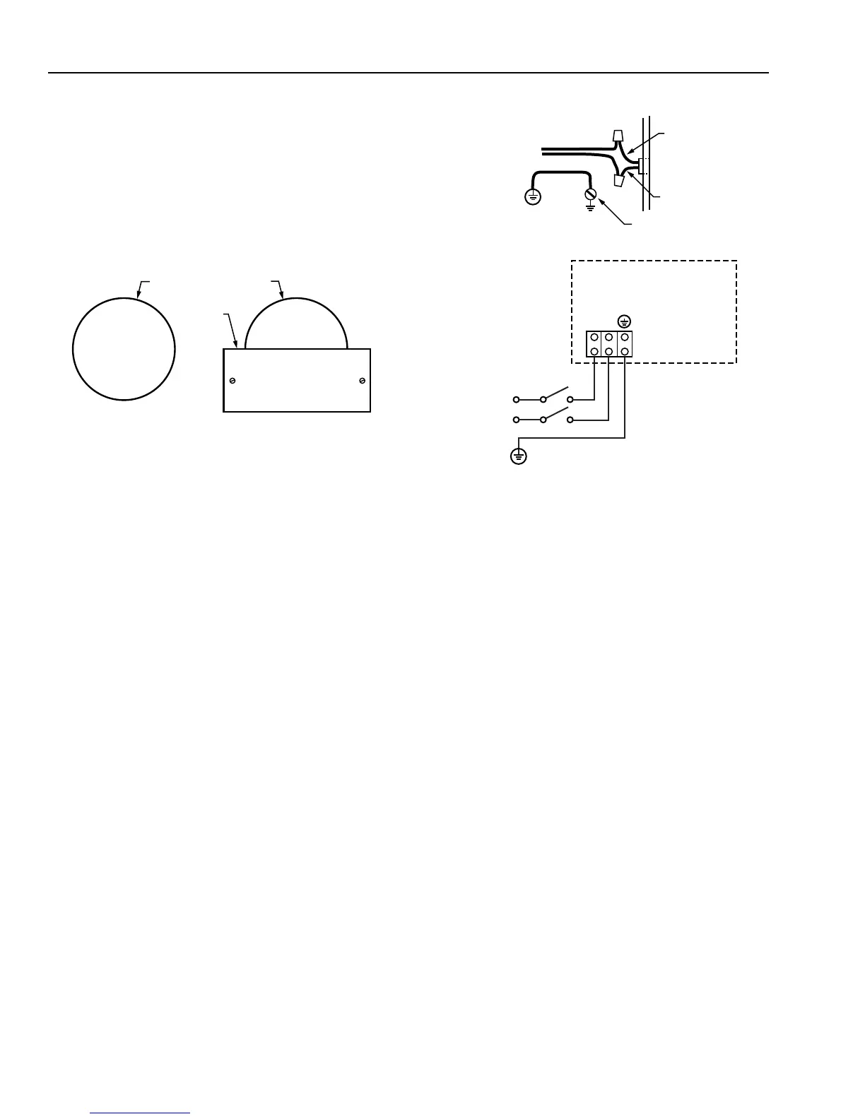
To wire 220–240 Vac, 50 Hz model, see Fig. 8.
IMPORTANT
Earth (ground) the F57 for proper operation and
safety.
120VAC, 60 HZ MODEL
BLACK FROM F57
WHITE FROM F57
BLACK
WHITE
120VAC
F57 GROUND SCREW
220-240VAC, 50 HZ MODEL
F57A / F57B
N
N
L
L
220-240VAC
M5669A
Fig. 8. Typical F57 wiring hookups.
Reassemble the F57
Reinstall the electronic cells, prefilter, charcoal filter (if used)
and grille assembly. For proper installation of the cells, see
Service section.
CHECKOUT
Inspect the Installation
Refer to Figs. 9 and 10 for location of components.
• Be sure that the screws on the back of the F57 are
removed to allow for the motor floating suspension.
• Observe that the F57 is oriented for good air circulation.
• Check that the F57 is correctly and securely attached. Be
sure that the F57 weight does not overstress the
suspended ceiling.
• Make sure that the access door is easily opened, and that
the prefilter, cells, and activated carbon filters (if used) are
secure within the unit.
• Check leveling of the F57. If necessary, further reinforce
and relevel suspended ceiling T-bar grid and adjust the
hanging wires. If unit is not level, motor can be noisy or
can eventually malfunction.
• Check that the electronic cells are correctly oriented for
correct airflow. The cells are correctly oriented when the
contact board of the cell is properly seated. The ionizer
section faces the access door and the collector section
faces the fan.
 Loading...