One Fire-Lite Place
Northford, CT 06472-1653 USA
203-484-7161 • FAX 203-484-7118
www.firelite.com
ANN-80 Series Annunciators
Product Installation Document
PN 52749:D3 9/30/2021 ECN: 4925
General
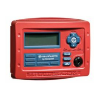
The ANN-80 Series Remote Fire Annunciators and Indicators (ANN-80,
ANN-80-W, ANN-80C) are compact, backlit LCD displays designed for
use with compatible FACPs (Fire Alarm Control Panels). The displays
mimic the FACP display and are capable of displaying English-language
text of system point status including device type, independent point
alarm, trouble or supervisory zone and custom labels programmed into
the FACP. Refer to the FACP manual installation section for detailed
system information and wiring.
Specifications
TB1 Terminals 1 & 2
Operating Voltage Range: 18.8VDC to 38.2VDC
Maximum Current Consumption:
• Normal/Standby (no activity): 39 mA
• Trouble Condition: 46 mA
• Alarm: 48 mA
• AC Fail (not backlit): 15 mA
TB1 Terminals 3 & 4
ANN-BUS rated at 5.5 VDC and 60 mA max.
Dimensions
6-7/8”W x 5-3/8”H x 1-3/8”D
Mounting
The ANN-80 Series plastic enclosures can be surface or semi-flush
mounted in a single, double or 4” square electrical box.
To mount the ANN-80 Series enclosure:
1. Open the ANN-80 Series cover by turning the key switch
counterclockwise to the ON (Unlocked) position.
2. Push in the snap latch tab located on the right side while pulling the
cover open.
3. Pull wire through 7/8” hole in backplate and feed through wire
channel to lower left corner of backplate before routing to terminal
block (refer to appropriate FACP manual).
4. The cover must remain attached to the backplate while mounting
the annunciator to the electrical box/wall. The cover cannot be
reattached or removed after the annunciator has been mounted.
5. If the cover should become detached from the backplate, reattach as
shown below.
6. Surface or Semi-flush mount the ANN-80 to a single, double or 4”
square electrical box. The ANN-SB80KIT(-R/-B/-W) is an
available kit that contains two plastic backboxes that can be used to
surface mount the ANN-80 Series.
Wiring the ANN-80 Series to the FACP
Refer to Table 1 and Figure 3 for wiring connections.
NOTE: Installation and wiring must be done in accordance with
NFPA 72 and local wiring codes.
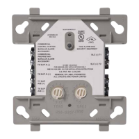
Backplate
Press in latch
and then
Pull open cover
Key switch shown
in OFF position
Cover with
LCD Display
Figure 1 Opening the ANN-80 Series
ANN-80 Series
Terminals (TB1)
FACP ANN-BUS
Terminals
Terminal 1 (-) (-)
Terminal 2 (+) (+)
Terminal 3 (A) A (ANN-BUS)
Terminal 4 (B) B (ANN-BUS)
ANN-80 Series
Terminals (TB2)
FACP ANN-BUS
Terminals
Terminal 1 Earth Ground
Table 1 ANN-80 Series to FACP Connections
ANN-80
Series
Cover
ANN-80
Series
Cover
ANN-80
Series
Backplate
ANN-80
Series
Backplate
• Position cover behind
backplate.
• Align hinge posts and
holes
• Slide holes down
onto posts.
• Close cover to lock
hinges into place.
Figure 2 Cover Reattachment