2
Bus Line Zone numbe
RIO Address
Zones
Zones are the individual input circuits on Galaxy systems
and are fully programmable in menu 52=Zones.
Zone Address Format
1 0 1 5
Galaxy zones are given addresses rather than zone
numbers. This is because the zones are grouped into
blocks of 8 called ‘RIOs’. The left hand digit is the data
bus line number. The second and third digits are the RIO
address, which can be 00 to 15. The right hand digit is the
individual zone number on the RIO (1-8). Each zone can
also be given a text descriptor. By default, it is blank.
There are 2 RIOs on board the panel (Line 1). The first
RIO (00) has 8 zones addressed 1001 to 1008 and the
second RIO (01) has 8 zones addressed 1011 to 1018.
All individual zone programming is done in menu 52.
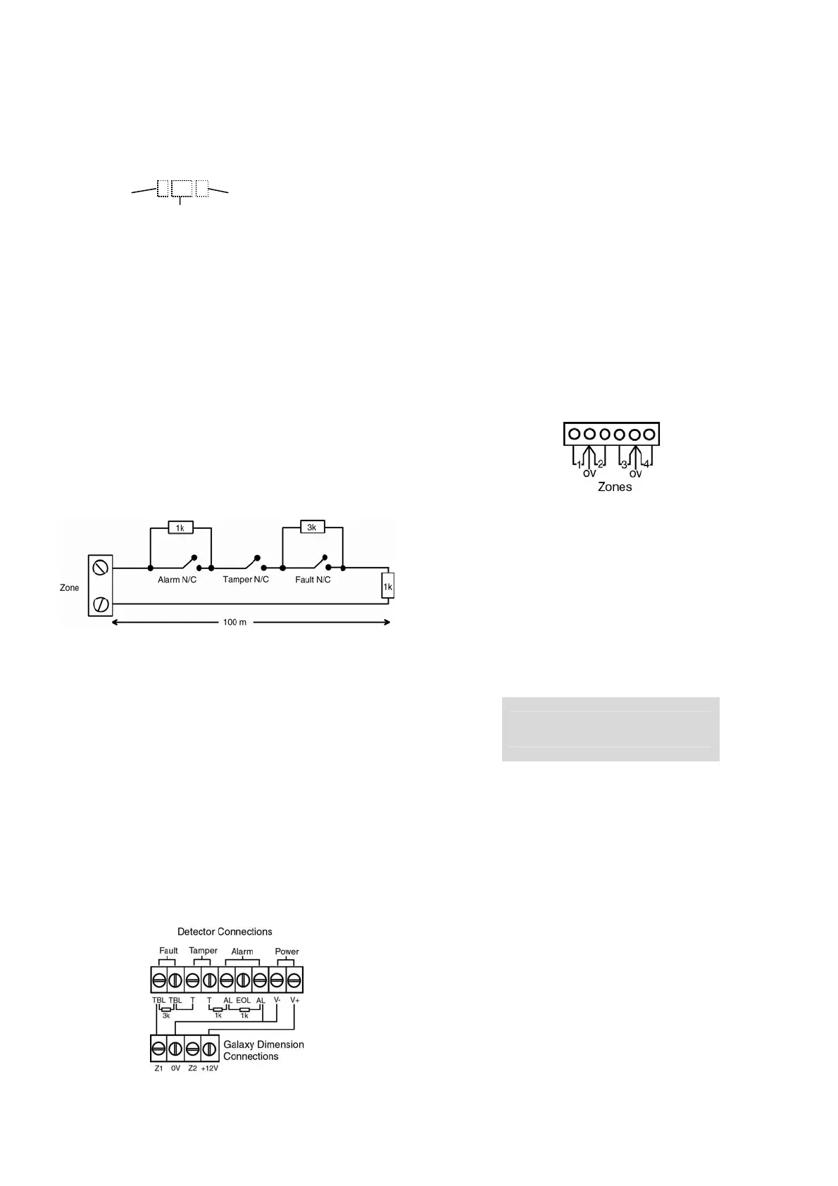
Zone Wiring
The default zone configuration is 1k double-balanced with
fault monitoring via a 3k resistor (preset 9). In the
following configuration a mask condition is generated if
an alarm and fault are signalled at the same time.
If no fault output is available, a mask output can be fitted
with a 12k resistor as an alternative.
Any unused hardwire zones should always have a 1k
resistor wired across the zone terminals to terminate them.
The configuration for the zones and the resistance preset
values used can be reprogrammed from menu option 51.46
= Zone Resistance. Each zone on the system can be
further customised to a specific preset by using menu
option 52.9=Resistance Select. The cable run on each
zone should be no more than 500 m. For presets 9 and 10
the cable run should be no more than 100 m.
Detector Wiring
Detectors are wired to a zone as in the following diagram:
Outputs
Galaxy outputs are addressed in the same way as the
zones. However, there are only 4 outputs on each RIO.
The on-board outputs are on RIO 0 and RIO 1. The
addresses are 1001 to 1004 (RIO 0) and 1011 to 1014
(RIO 1).
All individual output programming is done in menu 53.
Output Wiring
The on-board outputs are all open-collector switched
negative. The load that is to be controlled by an output
should be connected between +12 V and the output
terminal. Output 1002 is a voltage-free relay output.
Power Wiring
Auxiliary power can be drawn from the terminals marked
+12V. The‘common’ terminals on the zones are 0 volts.
Terminals marked GND are also 0 volts.
Operation
Default User Codes
Default User Code: 12345
Default Engineer Code: 112233
First Boot-up
After all the peripherals have been wired and addressed,
apply power to the system. The keypads will configure and
show the default banner display.
Galaxy <XXX> <VY.YY>
09:00 SAT 01 JAN
Where: XXX = Panel type, VY.YY = Panel software version.
Memory
Remove the Card fitted under the retaining clip on the
memory backup battery. This retains the panel memory for
up to 1 year in the event of a complete power fail.
To completely erase the system memory and return to the
default settings, replace a piece of thin card between the
retaining clip and battery then remove all power to the
PCB for one minute. Re-apply power and remove the card.
This is known as a cold start.
Menu Access Operation/Navigation
Only valid codes can access the Galaxy Dimension menu
options. Type the code then press ent to access the menu.
Data entry is via the 0-9 function keys and the * and # on
the keypad.
The A> and <B keys are cursor or scroll keys and are used
to scroll through options in menus.
 Loading...


