HE220, HE260 HUMIDIFIER INSTALLATION KIT
69-2518—03 6
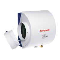
IMPORTANT
With low-speed airflow or variable speed sys-
tems it is recommended to run tubing to both the
supply and return ducts.
Fig. 12. Install tubing.
You may cut the tubing to fit the connection length
between the tubing fitting elbow and switch. It is also
recommended to secure the hose to existing structures to
avoid accidental disconnection.
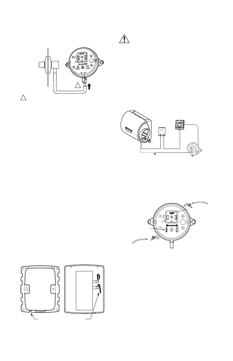
INSTALLING HUMIDISTAT
Mounting Duct
1. Apply the template to the duct location chosen for
the humidistat. Make sure the template is level
before drilling the holes.
2. Refer to the template (provided with the H8909
Humidistat Installation Instructions) to drill the con-
trol assembly opening and mounting holes for the
H8908.
3. Remove the H8908 case from the base.
4. Position the foam gasket on the H8908 base.
5. Position the base on the duct with the arrow up.
6. Secure the base to the duct using the four
1 in. (25 mm) mounting screws provided with humi-
distat.
7. Connect the low-voltage wires to the leads and
replace the H8908 case. See Fig. 14.
NOTE: For wall mounting instructions, see the H8908
Installation Instructions.
Fig. 13. Humidistat base and rear view.
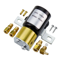
WIRING
Hazardous Voltage.
Can cause personal injury or equipment
damage.
Disconnect power supply before installing or
servicing equipment.
IMPORTANT
All wiring must comply with applicable local
code, ordinances and regulations.
Wire the humidifier solenoid valve, pressure switch,
humidistat and transformer.See Fig. 15
Fig. 14. Wiring the controls.
Fig. 15. Close-up of pressure switch wiring.
1. Run the two-strand thermostat wire from the humid-
ifier to the transformer, from the transformer to the
humidistat, and from the humidistat to the pressure
switch.
2. Cut lengths of thermostat wire to reach between
components, leaving adequate wire at both ends for
connections.
NOTE: Transformer, humidistat and pressure switch can
be wired in any order.
3. At the humidifier, connect the black and white con-
ductors to the two black humidifier wires.
4. At the transformer, connect both black conductors
to the two transformer terminals. Use a wire nut to
connect together the two white conductors.
M27304
INSIDE
OF DUCT
CONNECT TUBING TO + CONNECTION IF PRESSURE TAP IS
MOUNTED TO SUPPLY DUCT. CONNECT TO – IF PRESSURE
TAP IS MOUNTED TO RETURN DUCT.
1
1
M20179
WIRE SLOT
HUMIDISTAT WIRES
HUMIDISTAT BASE REAR OF HUMIDISTAT
M28974
HUMIDIFIER
SOLENOID
VALVE
H
u
mid
i
ty
Contro
l
Régulat
eur d'h
u
m
i
d
it
é
-2
0 ¡F
-
10 ¡F
0 ¡F
+10
¡F
+2
0 ¡F
O
ve
r 20 ¡F
1
5%
20%
25%
30
%
3
5%
40%
H
UMIDITY
SET
TIN
G
OUTD
OOR
TEMPER
ATUR
E
-30 ¡C
-25
¡C
-2
0
¡C
-10 ¡C
-5 ¡C
Over 0 ¡C
HUMIDISTAT
AIR PRESSURE
SWITCH
TRANSFORMER
ATTA CH
ADAPTOR
WIRE TO HVAC
C TERMINAL
M27398A
COMMON (C) TERMINAL
1/4 (6) X 1/32 (1) THICK
QUICK CONNECT
NORMALLY OPEN (NO)
TERMINAL 1/4 (6) X 1/32 (1)
THICK QUICK CONNECT
ATTACH ADAPTER
WIRE TO HUMIDIFIER
C TERMINAL
C
1
2
3
1
2
3
2
3
NC
NO
+
PI
ASSEMBLED
IN MEXICO
 Loading...