Before You Begin
Before you begin, check that you have received all of the parts listed below. If any parts are missing
or damaged, contact your dealer immediately.
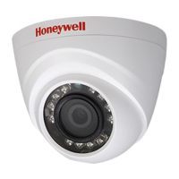
HED1PR3/HED3PR3 True Day/Night Indoor/Outdoor IR Ball IP Camera
Mounting the Camera
1.
Route the cables through the camera base.
2.
Align the screw holes on the camera base with the plastic wall anchors.
3.
Insert the three self-tapping screws through the holes in the camera base, into the wall
•
Camera
•
Documentation CD
•
Quick install guide
Required tools:
•
A Phillips screwdriver
•
Self-tapping screws (×3)
•
Plastic wall anchors (×3)
•
Mounting template
anchors, and then tighten them to secure the camera base in place.
Installing and Adjusting the Ball Camera
1.
Connect the Ethernet cable to the RJ-45 port on the ball camera.
2.
If the other end of the Ethernet cable is NOT connected to a PoE (Power-over-Ethernet)
switch or NVR, connect the power connector of the camera to a 12-V DC power source.
3.
Reattach the cover to the base, and then move the ball camera body to the desired position.
CAUTION
Installation and servicing should be performed only by qualified
and
experienced technicians to conform to all local codes and to maintain your
warranty.
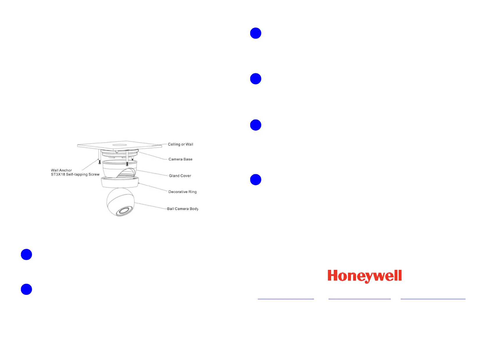
Installing the Decorative Ring
Ceiling or wall
Wall anchor
Camera base
ST3x18 self
Gland cover
Decorative ring
Ball camera body
When you have achieved the desired field of view with the camera’s web viewer or a NVR’s display,
install the decorative ring.
1.
Align the three tabs on the decorative ring with the slots on the camera base.
2.
Turn the decorative ring clockwise until it securely clicks into place.
Logging On to the Camera
Camera connected to a PoE port of the Honeywell Embedded NVR can be configured with the NVR
directly.
To log on to the camera with a PC, install the Honeywell Config Tool from the software and
documentation CD, find the camera and open the web browser with the Honeywell Config Tool. The
default user name is admin (case-sensitive) and the default password is 1234.
Removing the Ball Camera from the Base
Turn the decorative ring clockwise out of the camera base and separate the gland cover from
the camera base. Set the ball camera body aside.
Preparing the Mounting Surface
1.
Place the mounting template on the mounting surface where you want to install the camera.
2.
Drill three (3) holes in the mounting surface for the wall anchors. Insert the wall anchors.
3.
Drill an appropriately sized hole and pull the cables through the mounting surface.
Document 800-21229V1 – Rev A – 10/2015
© 2015 Honeywell International Inc. All rights reserved. No part of this publication may be reproduced by any means without written permission from Honeywell. The information in this publication is believed to be accurate in all respects. However,
Honeywell cannot assume responsibility for any consequences resulting from the use thereof. The information contained herein is subject to change without notice. Revisions or new editions to this publication may be issued to incorporate such changes.
www.honeywell.com/security
+1 800 323 4576
(North America only)
www.honeywell.com/security/uk
+1 44 (0) 1928 754 028
(Europe only)
www.asia.security.honeywell.com
+86 21 22196888
(Asia Pacific only)
1
2
4
•
A drill with an appropriately-sized drill bit for pre-drilling holes for the screw.
 Loading...