Do you have a question about the Honeywell HERMetic UTImeter Gtex and is the answer not in the manual?
| Operating Temperature | -20 °C to +50 °C (-4 °F to +122 °F) |
|---|---|
| Intrinsically Safe | Yes |
| Application | Tank gauging |
| Measures | Temperature |
| Approvals | ATEX, IECEx |
Unique identifier for each HERMetic instrument, found on the identification plate.
Glossary of terms used to define the equipment and its components.
Lists the components included in the instrument shipment.
Instructions for checking shipment completeness and initial instrument functionality.
Notes on potential minor changes from manual details due to continuous development.
Details the warranty period and conditions for the instrument.
Information on ISO 9001 certification and intrinsic safety approvals.
Guidance on identifying and ordering spare parts for the equipment.
Procedures and responsibilities for instrument service and repair.
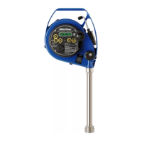
Provides an overview of the HERMetic instrument, serial number, and beep signals.
Details the ULTRA sensing probe, including its components and measurement capabilities.
Describes the ETFE coated tape, its functions, and graduation.
Explains the mechanical safety device that prevents valve closure with the probe inside.
Explains how the reading index on the instrument indicates tape distance for measurements.
Describes the tape cleaner mechanism for draining liquid and its operation.
Details how the device achieves gas tightness through seals and gaskets.
Specifies the materials used for gaskets in different UTImeter Gtex models.
Describes the optional additional load for the sensing probe for specific measurements.
Information on the material and construction of the housing and lid.
Other components and features like tape coiling and storage tube connector.
General considerations for mounting the HERMetic equipment with MMC adaptors.
Illustrates installations with different adaptors and valve types.
Explains the function of the 5-key control pad for navigating menus and settings.
Step-by-step guide to select the display language for the UTImeter.
Instructions for choosing between Celsius or Fahrenheit for temperature readings.
Guide to setting the temperature display resolution (1 or 2 decimal digits).
Describes how to enable temporary or permanent LED activation for status indication.
Procedure to mute the instrument's buzzer, with notes on automatic reactivation.
How to activate the display backlight for night use, with auto-off feature.
Recommended tests to ensure the instrument is ready for operation.
Steps for correctly installing the HERMetic instrument onto a certified valve.
Information on the optional purging feature for the equipment.
Procedure for performing ullage and interface level measurements.
How to measure reference height and innage using the optional load feature.
Procedure for accurately measuring the temperature at different levels within a tank.
Guidelines for cleaning and storing the instrument to maintain its condition.
How to check the battery status before and during gauging operations.
Step-by-step instructions for replacing the instrument's battery safely.
Procedures for disconnecting and replacing the tape assembly.
Instructions for disconnecting and connecting the sensing probe.
How to easily replace the tape wipers in the tape cleaner.
Steps for disconnecting and connecting the display unit.
Guidance on periodic inspection and verification of tape accuracy and integrity.
Instructions for verifying and adjusting the instrument's reading index.
Procedure for checking the temperature accuracy of the UTImeter annually.
How to verify the ullage and interface level detection capabilities of the instrument.
Critical safety precautions for performing repairs or troubleshooting.
Identifies symptoms and actions for power supply related issues.
Lists symptoms and recommended actions for transmission signal problems.
Diagnoses and solutions for issues related to ullage and interface measurements.
Troubleshooting steps for problems with temperature readings.
Guidance on inspecting the instrument for physical damage or missing components.
Inspection criteria for the protective coating on aluminium parts.
Simple process to resolve stiff winding action of the tape mechanism.
Procedures for testing tape grounding, short-circuit, and continuity.
Instructions on how to identify and order spare parts using TS numbers.
A table listing descriptions and TS numbers for various spare parts.
References to drawings and documentation for spare parts and compliance.