EasyManua.ls Logo

Honeywell HM750 User Manual

Honeywell HM750
28 pages
To Next Page IconTo Next Page
Page #1 background imageLoading...
Page #1 background image
INSTALLATION INSTRUCTIONS
33-00289-01
IMPORTANT
Read and save these instructions. This guide should be kept by the installer.
HM750A1000
ADVANCED ELECTRODE STEAM HUMIDIFIER
INTRODUCTION
The HM750 is the most advanced residential steam
humidifier available and provides steady and reliable
humidification for a home. The humidifier is designed for
connection directly to a supply air duct for humidity on
demand. The humidifier may be directly mounted to the air
duct, or remotely from the air duct, with a steam hose
connecting the humidifier to a distributor nozzle installed
at the air duct.
Included in the Box
HM750 steam humidifier
H6062 HumidiPRO
Steam distributor nozzle
Rubber drain hose
LDPE water hose
Baffle (duct mount only)
Foam gasket (duct mount only)
Steam hose (wall mount only)
Fittings, hardware, and mounting template
Installation Instructions, 33-00289 (this document)
Annual Operation and Maintenance Reminder
Tools Needed
Flat-head screwdriver
Phillips screwdriver
—Wrench
Copper pipe (optional)
Level
—Hole saw
Humidifier Configuration
The HM750 is configured at the factory to operate under
most conditions without the need to change its
configuration.
NOTE: Because the humidifier is factory configured for
optimal performance, Honeywell strongly
discourages changes to the configuration of the
humidifier not described in these instructions.
Before Installation
1. Ensure that available voltage and phase
corresponds with humidifier voltage and phase as
indicated on humidifier’s specification label.
2. Ensure that the dedicated external fuse disconnect
is of sufficient size to handle the rated amps as
indicated on the specification label. Refer to local
codes.
3. Ensure sufficient clearances will be available as
described in the Location section on page 6.
4. If the humidifier will be wall mounted, ensure steam
lines can be routed to duct as described in the Steam
Line Instructions on page 7.

Table of Contents

Question and Answer IconNeed help?

Do you have a question about the Honeywell HM750 and is the answer not in the manual?

Honeywell HM750 Specifications

General IconGeneral
ControlAutomatic
Voltage120V
SpeedsVariable
Tank CapacityN/A (direct water supply)
Run TimeContinuous operation
HumidistatIncluded

Summary

INTRODUCTION

Tools Needed

Lists the tools required for installation.

Humidifier Configuration

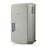
Explains the factory configuration of the humidifier.

Before Installation

Key checks and considerations before starting the installation process.

Parts and Accessories

How the Humidifier Works

Explains the operational principles of steam generation, distribution, and drainage.

SIZING

LOCATION

Steam Nozzle Location

Details the rules for positioning the steam distributor nozzle in the air duct.

Steam Line Instructions

Main Rules for Atmospheric Steam Lines

Outlines key rules for installing atmospheric steam lines.

Steam Distributor Nozzle

Explains installation of the steam distributor nozzle for remote mounting.

Steam Line Installation Examples

MOUNTING THE HUMIDIFIER

Mounting to a Wall

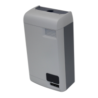
Details the process for mounting the humidifier to a wall stud.

Mounting to the Supply Duct

Explains how to mount the humidifier directly onto the supply air duct.

PLUMBING

Connecting the Water Supply Line

Guides on connecting the water supply line to the humidifier.

Connecting the Drain Line

Details how to connect the drain hose to the humidifier.

ELECTRICAL

Voltage Selection

Explains how to select the correct operating voltage (120VAC or 240VAC).

Connecting Power

Outlines the requirements and procedure for connecting electrical power.

Low-voltage Controls

Wiring Procedure

Explains the procedure for connecting low-voltage controls to the humidifier.

Humidistat or Thermostat Connection

Describes connecting a humidistat or thermostat to the HUM terminals.

Air Proving Device

Explains the use and connection of an air proving device to AP terminals.

Fan Interlock

Details connecting an external fan to the EXTERNAL terminals.

Humidity Control Placement

Provides guidance on optimal placement for humidity control devices.

START UP

Installation Check

Procedures to verify correct installation before powering on the unit.

Start Up Procedure

Step-by-step guide to power up and initiate the humidifier.

OPERATION

LED Status Lights

Explains the meaning of various LEDs on the humidifier interface.

Selecting a Relative Humidity Setpoint

Guidance on setting the optimal humidity level for the space.

MAINTENANCE AND SERVICING

Required Maintenance

Lists essential maintenance activities like checking the cylinder and cleaning components.

Extended Shutdown

Procedure for safely disconnecting power for an extended period.

Starting After Extended Shutdown

Steps to follow when restarting the humidifier after extended shutdown.

REPLACEMENT PARTS

Cylinder Spent Fault

Explains the yellow LED indicator for a spent cylinder and replacement necessity.

CYLINDER REPLACEMENT KIT

Details the cylinder replacement kit, including parts and tools.

Removing the Cylinder

Drain Valve Removal

Inlet Valve Strainer Cleaning

CONTROL BOARD REPLACEMENT

Opening Electrical Compartment

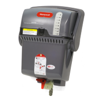
Steps to safely open the electrical compartment to access the control board.

Removing the Control Board

Detailed steps for removing the existing control board.

Installing the Control Board

Procedure for installing the new control board and reconnecting wires.

Inlet Valve Replacement

TROUBLESHOOTING

HM750 Faults

Clearing a Fault

Instructions on how to clear detected faults using the Power/Drain button.

5 YEAR WARRANTY

Related product manuals