Installation NAC Circuit Wiring
20 HPFF8(E)/HPFF8CM(E) NAC Expander — P/N 53499:B4 10/1/2018
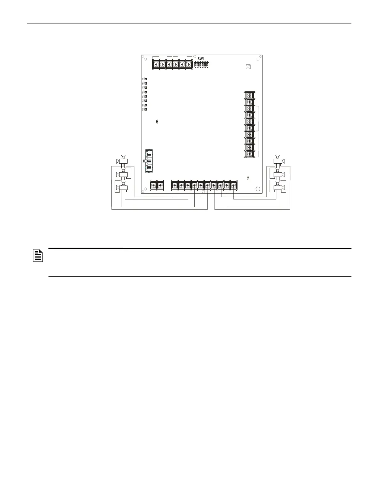
2.4.2 Two NACs Configured for Class A (Style Z)
Figure 2.11 shows two NACs configured for Class A (Style Z).
+
-
+
-
+
-
+
-
-
+
-
+
-
+
-
+
TB3
TB4
TB1
TB2
SW2
LEDs
REF+ REF– + IN – IN
+ OUT
– IN
+ OUT+ OUT
+ IN
– OUT
SIGNAL 1
SIGNAL 2
BATT+ BATT–
A+
N/O
N/C
COMM
N/O
N/C
COMM
AC FAIL
TROUBLE
J1
J2
1L1 1L2 2L1 2L2
3L1 3L2
4L1 4L2A–
NAC 1 NAC 2
f
f
8
1
2
n
a
c
c
l
a
s
s
a
.
w
m
f
Horn Strobe
Horn Strobe
Horn Strobe
Alarm Polarity
Shown
• Trouble on NAC1 will illuminate
LED1 SIG1 TRBL and
LED2 SIG2 TRBL
• Trouble on NAC2 will illuminate
LED3 SIG3 TRBL and
LED4 SIG4 TRBL
No ELR required for Class A wiring.
Figure 2.11 Two NACs in Class A (Style Z)
NOTES:
1. Typical ELRs for new installations can be 3.9k or 4.7k ohm.
2. The same gauge wire must be used if two conductors are connected to the same terminal of any terminal block.
3. Do not complete a continuous circuit around the screw terminal. There must be two separate wires on either side of the screw at the
terminal block. “T-tapping” is absolutely NOT ALLOWED.

 Loading...

