F. Installing the Antenna
The antenna comes with an SMA connector, which provides
easy connection with the communicator.
Important
• Do not use a damaged antenna with the communicator.
Replace the damaged antenna immediately.
• Use only a manufacturer approved antenna. Non-approved
antennas or modifications could impair service quality,
damage the device, and violate FCC regulations.
• A location below the ground level or a metal structure may
impact the network coverage.
• The antenna should be positioned perpendicularly to the
ground, either right side up or upside down.
• Keep the antenna away from any sources interfering with or
blocking the RF signal.
For example, a metal object may shield the cellular radio RF
signal.
• The antenna should be at least 7.8" (20 cm) away from
people.
• The antenna must not be co-located or operating with any
other antenna or transmitter.
• Ensure that the panel supplies 24V DC power from its
constant power output.
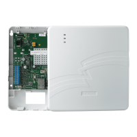
To Connect the Antenna
1. Route the antenna cable through the small rubber grommet
located on the top-left side of the enclosure.
2. Attach the magnet at the bottom of the antenna onto the top
wall of the enclosure.
3. Locate the antenna connector on top of the communicator.
4. Thread the antenna cable end onto the antenna connector and
tighten it.
5. Loop the excess cable length inside the enclosure.
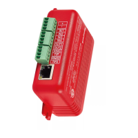
G. Wiring for Dialer Capture
For dialer capture, you connect both dialer ports of the fire panel
with the communicator.
All wiring must be within a conduit.
Preparations
• For panel dialer ports with 8-pin RJ type connectors, use an
RJ45 connector with the other end as a pigtail.
• Use only the Pin 4 wire, which is typically Blue with White
stripe, for RING connection.
• Use only the Pin 5 wire, which is typically solid Blue, for TIP
connection.
• Cut all other wires.
To Wire the Panel with the Communicator
Figure 2: The Wiring Diagram
H. Powering ON
1. Power ON the communicator and the panel.
2. Ensure that the panel and communicator are receiving
required power.
I. Activating the CLSS Pathway
A panel event activates the CLSS Pathway communications.
Create a test event and check that the device is activated.
J. Verifying the Connections
Troubleshooting
If no events are received: Verify the RING and TIP connections.
Then, check for communication failure error messages at the
panel and fix the error, if any. Disable the Wait for Dial Tone
options in the panel.
Cellular Connectivity issues: Go to the Device Registration screen
on the CLSS App. Ensure that the signal strength shown on it is
at least one to two bars. Reposition the antenna for higher signal
strength.
Panel’s
Terminal
Connector Steps
AUX
+
Connect to AUX + of the
Communicator.
GND
-
Connect to GND of the Communicator.
Primary
Dialer
RING Connect to RING of the Communicator.
TIP Connect to TIP of the Communicator.
Backup
Dialer
RING2 Connect to RING2 of the
Communicator.
TIP2 Connect to TIP2 of the Communicator.
The Green
LED is
Indication Suggested Steps
Constantly
ON
Connected with
good signal
None
Fast
Flashing
Transferring data None
Slow
Flashing
Attempting
connection despite
signal issues
Reposition the antenna.
Flashing
every 5
seconds
Connected despite
the low signal
Reposition the antenna.
Troubleshooting
OFF
Communicator is
not connected to the
panel
Verify that the wiring is as
per the wiring diagram
No power from the
panel
Measure and ensure required
AUX output from the panel
Damaged
communicator
Replace the communicator
2
© 2021, Honeywell International Inc.
12 Clintonville Rd.
Northford, CT 06472
(203) 484-7161
Technical Support: CLSS.Tech@Honeywell.com
Agency Listings and Approvals
These listings and approvals apply only to the communicator specified in this
document. In some cases, listing may be in process.
FCC Statement
This equipment complies with FCC rules Part 15.
ETL Listed
Control No. 5013005
UL Standards
The HW-AV-LTE-M is designed to comply with UL 864 - Control Units and
Accessories for Fire Alarm Systems Units
Serial Number and Configuration Key
Remove the sticker below and apply to inside the communicator
enclosure lid. This will be used during CLSS communicator
programming and for future reference.
 Loading...