Do you have a question about the Honeywell NOTIFIER UDACT and is the answer not in the manual?
Warning regarding the generation and potential interference of radio frequency energy.
Compliance information for Canadian digital apparatus radio noise emissions.
Provides information for installing, programming, and operating the UDACT.
Details compliance with UL 864 standard for control units and accessories.
Lists documents for supplemental information related to control panels.
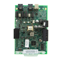
Explains UDACT's function and connection to Central Station Receivers.
Lists the key features and capabilities of the UDACT device.
Describes the front panel membrane switches and LEDs for UDACT operation.
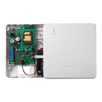
Lists Fire Alarm Control Panels compatible with the UDACT.
Details the functions of the UDACT's integral digital communicator.
Explains the EIA-485 communication and other circuits used by the UDACT.
Lists technical specifications including power, data communications, and outputs.
Covers telephone line requirements and FCC warnings for UDACT installation.
Describes the different operating modes of the UDACT.
Provides information on UDACT installation options and procedures.
Details the 24 VDC power connection for the UDACT.
Explains the EIA-485 serial interface connection for communication.
Describes how to connect the UDACT to telephone lines.
Details connections for the UDACT's auxiliary output for communicator failure.
Outlines UL requirements for power-limited wiring separation.
Introduces UDACT programming capabilities and storage.
Step-by-step guide on how to access the UDACT programming mode.
Explains the function of each switch on the UDACT keypad in program mode.
Details various programming options and their corresponding addresses.
Covers event codes for primary and secondary numbers for these formats.
Covers event codes for primary and secondary numbers for these formats.
Details event codes for primary and secondary numbers using Ademco Contact ID.
Provides reference sheets for UDACT programming options and event codes.
Lists the default programming settings for various UDACT options.
Describes the standard operation mode, monitoring FACP status and phone line voltage.
Used to disable reports by zone/point or identify specific functionality.
For testing telephone line wiring and identifying faults.
Tests all system LEDs on the UDACT.
Shows data reporting structures for pulsed and Ademco Express formats.
Lists UL listed receivers compatible with the UDACT.
UDACT capability with AFP-100 regarding zones and points.
Instructions for mounting the UDACT internally or remotely with AFP-100.
Details wiring connections for UDACT with AFP-100.
Chart to identify function of each zone when used with AFP-100.
Chart to identify function of each point when used with AFP-100.
UDACT capability with AFP-200 regarding zones.
Instructions for remotely mounting UDACT with AFP-200.
Details wiring connections for UDACT with AFP-200.
Chart to identify function of each zone when used with AFP-200.
UDACT capability with System 500 regarding zones and inputs.
Instructions for remotely mounting UDACT with System 500.
Details wiring connections for UDACT with System 500.
Chart to identify function of each zone when used with System 500.
UDACT capability with System 5000 regarding zones and inputs.
Explains module slot positions and UDACT reporting for AIM-200.
Instructions for mounting UDACT with System 5000.
Details wiring connections for UDACT with System 5000.
Zone assignments for System 5000 with AIM-200 module.
Zone assignments for System 5000 without AIM-200 module.
UDACT capability with AFP-300/AFP-400 regarding zones and points.
Instructions for mounting UDACT with AFP-300/AFP-400.
Details wiring connections for UDACT with AFP-300/AFP-400.
How to use Type Mode for zone/point identification with AFP-300/400.
Event code and report transmission details for AFP-300/400.
Chart for zone assignments with AFP-300/AFP-400.
Chart for point assignments with AFP-300/AFP-400.
UDACT capability with NFS panels regarding zones and points.
Instructions for mounting UDACT with NFS panels.
Details wiring connections for UDACT with NFS panels.
How to use Type Mode for zone/point identification with NFS panels.
Event code and report transmission for NFS panels.
Chart for zone assignments with NFS panels.
Chart for point assignments with NFS panels.
UDACT capability with NCA panels regarding zones and points.
Instructions for mounting UDACT with NCA panels.
Details wiring connections for UDACT with NCA panels.
UDACT capability with AM2020/AFP1010 regarding points.
Instructions for mounting UDACT with AM2020/AFP1010.
Details wiring connections for UDACT with AM2020/AFP1010.
Chart for point assignments with AM2020/AFP1010.
UDACT capability with NFS2-3030/NFS-3030 regarding points.
Instructions for mounting UDACT with NFS2-3030/NFS-3030.
Chart for point assignments with NFS2-3030/NFS-3030.
Explains how UDACT affects annunciator LED assignments.
| Brand | Honeywell |
|---|---|
| Model | NOTIFIER UDACT |
| Category | Cell Phone |
| Language | English |