UDACT Instruction Manual — P/N 50050:M 12/18/2009 63
Appendix A: AFP-100 (UL 8th)
A.1 General
The UDACT is capable of reporting a maximum of 56 zones or 198 points when used with the
AFP-100. For more information on the AFP-100 see the AFP-100 Instruction Manual.
A.2 Mounting
A.2.1 Internal
The UDACT can be mounted in the AFP-100 cabinet by following the instructions and referring to
the figure below:
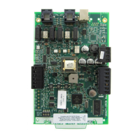
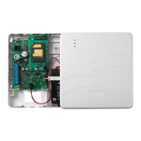
Figure A.1 UDACT Installation in AFP-100 Cabinet
Step Action
1 Disconnect all sources of power (AC and DC).
2 Install 3 nylon and 1 aluminum 5/8” long snap-in standoffs (provided)
in the holes located on the right side of the circuit board.
3 Place the SW2 switch in the down position to enable AC Loss Delay
Reporting.
4 Carefully connect the ribbon cable (PN 75306, provided) to connector
J16 on the circuit board and to connector J10 on the UDACT.
5 Align and snap the UDACT to the nylon standoffs.
6 Secure the UDACT to the aluminum standoff using the screw
provided. Tighten securely.
J10
PC/PRINTER
TERM COMM
TROUBLE
RS-232
PC/PRINTER
RS-485
TERM. MODE
A B B+ A+ B- A-
1 COMM 2
ACS
SHIELD SLC SLC
OUT+ IN+ OUT- IN-
T
B
7
T
B
5
T
B
6
J16
J6
JP4
SW1
SW3
SW2
GNDFAULT
UDACT-20.cdr
NYLON Standoffs
ALUMINUM Standoff
UDACT
AFP-100
Ribbon Cable attached
as illustrated at right
SW2 Switch

 Loading...