Do you have a question about the Honeywell GSMV4G and is the answer not in the manual?
Overview of the GSMV4G/GSMVCN4G communicator, its capabilities and new 4G connectivity.
Details on communicator signal transmission, SMS/email capabilities, and AlarmNet Remote Services.
Highlights basic features including Remote Services and quick connection to Honeywell panels.
Information on the 256-bit AES encryption used by the communicator for enhanced security.
Description of web-based services for remote system access and event notifications.
Overview of the four operational modes for compatibility with various control panels.
Technical specifications including mechanical, input power, current drain, and environmental details.
Information on compatible control panels and receivers for UL and ULC installations.
Details on ULC installation codes and standards the device complies with.
Guidance on selecting an optimal location based on signal strength for proper operation.
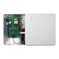
Instructions for physically mounting the GSMV4G/GSMVCN4G unit to a surface or gang box.
Specific procedures for mounting GSMV4G (no rear tamper) and GSMVCN4G (with rear tamper).
Details on connecting the communicator to power and other system components.
Instructions for connecting the optional audio cable for two-way voice functionality.
Wiring diagrams for ECP, 4204, and Two-4204 communication modes with control panels.
Guide for connecting triggers for Zone Trigger Mode using various input types.
How to wire the fault output trigger for fail-safe mode and communicator fault conditions.
Information on powering the communicator and available options for different installation types.
Details on different methods for powering the device: standard, ULC, and shared transformer.
Instructions for connecting the backup battery for power loss protection.
Steps to follow for the initial power-up of the device after installation.
How the communicator delivers alarms via GSM network to AlarmNet and requires an AlarmNet-i account.
Instructions for programming the communicator via the AlarmNet Direct website.
How to connect and use the 7720P Programming Tool for device configuration.
Using control panel programming mode for ECP Mode communicator configuration.
General guidelines and conventions for answering programming prompts and navigating menus.
Detailed prompts and options for programming the communicator in ECP mode.
Table of common ECP keypad display status codes and their meanings.
Programming for Zone Trigger, 4204 Emulation, and Two-4204 Emulation modes.
Steps to exit programming mode and upload configuration changes.
Instructions to reset programming options to factory-default values.
Overview of the registration process and LED status indications.
Steps for registering the communicator via the AlarmNet Direct website.
Method for initiating the registration sequence using the tamper switch.
Using the 7720P Programming Tool for interactive registration.
Common errors encountered during registration and their potential causes.
Procedure for registering a replacement communicator with PIN verification.
Instructions for registering the communicator by calling the AlarmNet Technical Assistance Center.
Overview of commands to view connectivity settings and options using the 7720P.
How to view MAC Address, SCID, and IMEI using keyboard commands.
Information on viewing GSM network status, signal strength, and registration.
How to view zone, tamper, power, battery, and fault status on the communicator.
LED indications for different operation modes (ECP, Zone, 4204) and signal strength.
LED indications for module status including GPRS service and registration.
Central station alarm and restore codes for ECP Mode.
Central station alarm and restore codes for Zone and 4204 Modes.
Panel-specific communicator trouble and radio fault messages.
Commercial panel specific trouble, signal loss, and radio fault messages.
Messages related to communication failure, radio substitution, and service termination.
| Network Technology | GSM / HSPA |
|---|---|
| 2G bands | GSM 850 / 900 / 1800 / 1900 |
| 3G bands | HSDPA 850 / 1900 / 2100 |
| GPRS | Yes |
| EDGE | Yes |
| Speed | HSPA |
| Network | GSM / HSPA |
| Display | 2.4 inch, 240 x 320 pixels |
| Operating System | Proprietary OS |