Section 2: Mounting and Wiring
2-7
Power Connections and Options
Powering the Communicator
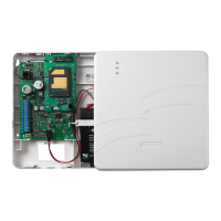
There are three ways to power the communicator (see illustrations below):
Standard Installation
– The communicator is powered by the supplied AC plug-in
transformer.
ULC Commercial Fire and Burglary Compliant Installation
– The communicator must be
powered by the control panel.
Shared Transformer Installation
– In this installation the supplied AC plug-in
transformer may be used to power both the communicator and the control panel under the
following conditions:
• You must use the Honeywell 1361 Transformer.
• This configuration ONLY applies to the VISTA-10P, VISTA-15P, VISTA-20P control
panels when used with the GSMV4G communicator.
• DO NOT use this configuration with any other control panel.
• DO NOT use this configuration if using two-way voice.
• This configuration has not been evaluated by UL.
For all installations the control panel ground (GND) must be connected to TB1-4 GND on the
communicator. In addition, if using ECP communication, you must connect the +12VDC
AUX voltage output on the control panel (9.6V-13.8V typical) to TB1-3 on the communicator.
Installation
ULC Commercial
Fire and Burglary
Compliant
Installation
 Loading...
