50 UDACT Instruction Manual — P/N 50050:M 12/18/2009
Operating Instructions Normal Mode
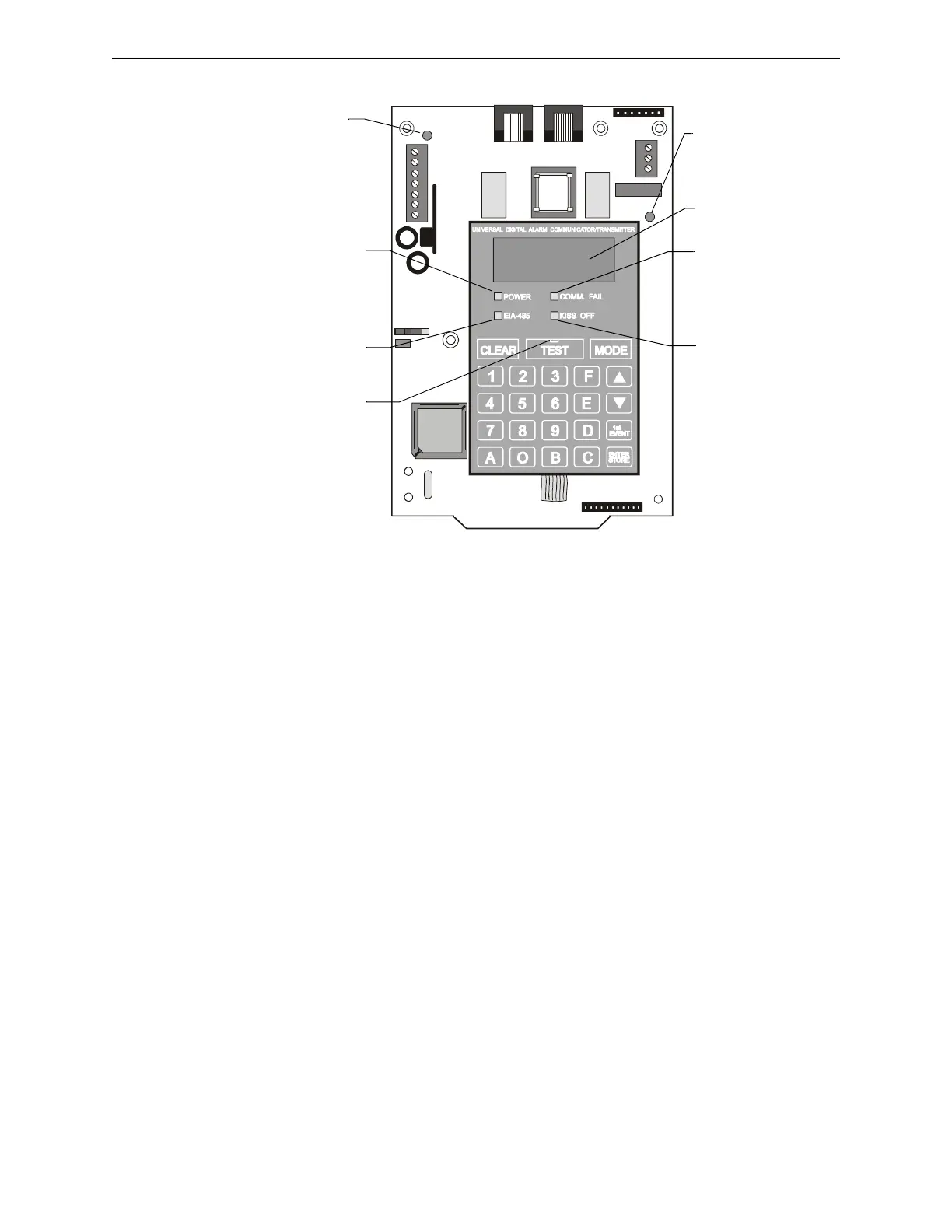
Seven individual LEDs are provided on the panel as described and shown below:
Figure 4.2 Display and LEDs
EIA-485 - A yellow LED that lights steadily when a fault on the EIA-485 circuit is detected.
Comm. Fail - This yellow LED lights to indicate the loss of both telephone lines or that the
maximum number of attempts to communicate with both Central Stations has been unsuccessful.
Note: During a comm fail, the display will show either a “PH 1” and “PH 2” or “no 1” and “no 2”.
Power - A green LED that remains lit while power is supplied to the UDACT. If this indicator fails
to light under normal conditions, service the system immediately.
Kiss Off - A green LED that flashes when the Central Station has acknowledged receipt of each
transmitted message.
Test - A green LED that lights to indicate that a manual test message is being transmitted and turns
off after messages transmit.
Primary Line Active - A red LED that indicates the primary phone line is active.
Secondary Line Active - A red LED that indicates the secondary phone line is active.
4.1.3 Normal Mode Operation
Normal mode is the standard mode of operation. In this mode, the UDACT monitors the following:
• Host FACP status, power input and EIA-485 communications.
• UDACT telephone line voltage.
The four character 7-segment display is normally off and does not annunciate events that are being
transmitted. The display will only annunciate UDACT trouble conditions in the normal mode.
The UDACT transmits zone/point and system status reports to a Central Station via the public
switched telephone network. Two supervised telephone line connections are made to interface the
UDACT to the telephone lines.
UDACT-01.cdr
COMM. FAIL
Yellow LED
KISS OFF
Green LED
EIA-485
Yellow LED
POWER
Green LED
Four, Seven
Segment Displays
Primary Active -
Red LED
(phone line)
Secondary Active -
Red LED
(phone line)
TEST
Green LED

 Loading...