82 UDACT Instruction Manual — P/N 50050:M 12/18/2009
AFP-300 & AFP-400 (UL 8th) Type Mode Programming
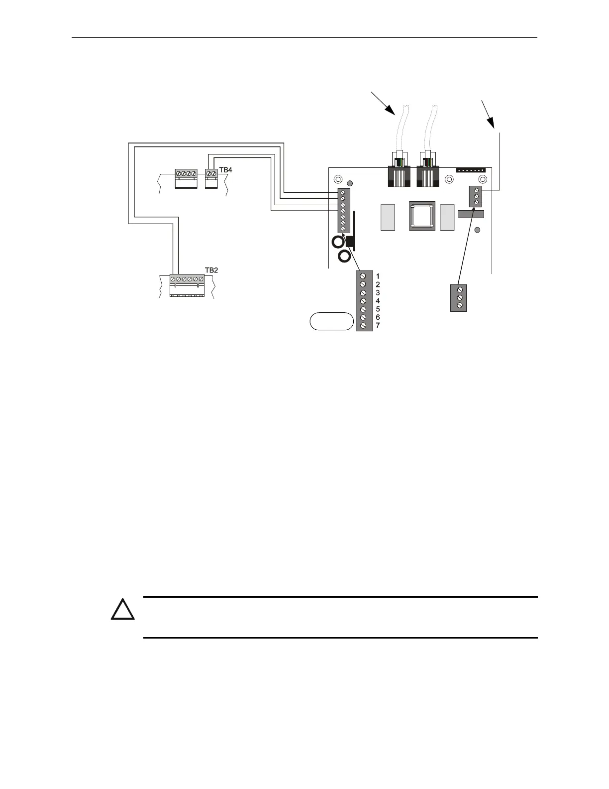
Below is an internal installation of a UDACT with an AFP-300/AFP-400:
Figure E.2 UDACT and AFP-300/AFP-400 in CAB-3/4
E.4 Type Mode Programming
To disable or identify a zone or point in Type Mode (refer to "Type Mode" on page 52), the
following Entries/Addresses are used:
E.4.1 For Zone Identification:
Zones 1 - 99 are programmed by Entries/Addresses 01 - 99. The factory default code is 'fire alarm.'
E.4.2 For Point Identification:
Loop 1, Modules 101 - 196 are programmed by Type Mode Entries/Addresses 01 - 96
Loop 2 Modules 201 - 296 are programmed by Type Mode Entries/Addresses 101 - 196
Loop 1, Detectors 101 - 196 are programmed by Type Mode Entries/Addresses 201 - 296
Loop 2, Detectors 201 - 296 are programmed by Type Mode Entries/Addresses 301 - 396
System 5000 output modules are programmed by Type Mode Entries/Addresses 401 - 464
EARTH
Comm FAILURE
+24V
+24V
GND
RS+
RS–
SHIELD
RS+
Rs–
ACS/TERM
TERM
DO NOT USE
MPS-400
CPU-300/400
To Phone Lines
(supervised)
Connect to CHS-4
Chassis
UDACT-14.cdr
!
CAUTION: Addresses 97 - 100, 197 - 200, 297 - 300, and 397-400 must not be programmed.
System 5000 output module addresses are dependent upon module location. Refer to the
CAB-B3, CAB-C3 and CAB-400AA illustrations on next page.

 Loading...