12 UDACT Instruction Manual — P/N 50050:M 12/18/2009
Overview Compatible Panels
1.7 Compatible Panels
The UDACT has been designed to be compatible with the following Fire Alarm Control Panels.
For current and compatible FACP firmware, refer to Magni-Fire.
• System 5000
• System 500
• AM2020/AFP1010
• AFP-100
• AFP-200
• AFP-300/400
• NFS2-640
• NFS-640
• NFS-320
•NCA
•NCA-2
• NFS-3030
• NFS2-3030
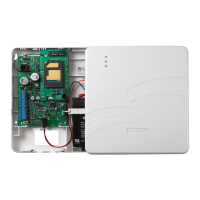
1.8 Digital Communicator
Two modular phone jacks allow easy connection to telephone lines. Modular jacks are labeled
“PH1” and “PH2” for the Primary and Secondary phone lines. Telephone line “Primary Active”
and “Secondary Active” red LEDs are provided as well as a green “Kissoff” LED. The integral
digital communicator provides the following functions:
• Line Seizure - takes control of the phone lines disconnecting any premises phones.
• Off/On Hook - perform on and off-hook status to the phone lines.
• Listen for dial tone - 440 hertz tone typical in most networks.
• Dialing the Central Station(s) number - default is Touch-Tone®, programmable to rotary.
• For tone burst or touchtone type formats: Discern proper “Ack” and “Kiss-off” tone(s) - The
frequency and time duration of the tone(s) varies with the transmission format. The UDACT
will adjust accordingly.
• Communicate in the following formats (refer to "Compatible Receivers" on page 61 for
compatible receivers):
6 Tone Burst Types: 20 pps (3+1, 4+1, 4+2)
3 Touchtone Types: 4 + 1 Ademco Express, 4 + 2 Ademco Express and Ademco Contact
ID
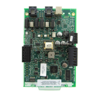
The UDACT circuit board contains a CPU, other primary components and wiring interface
connectors.
1.9 Circuits
1.9.1 Communications
Communications between the UDACT and the host control panel is accomplished over a two wire
EIA-485 serial interface which is power-limited and supervised by the control panel and the
UDACT. The wiring connections are made to the RS +, RS –, and Shield terminals of TB1 on the
UDACT.

 Loading...