Do you have a question about the Honeywell NOTIFIER UDACT-2 and is the answer not in the manual?
General guidance for problem-free installation and long-term reliability.
Covers critical warnings and cautions related to power, system changes, and testing.
Details FCC and Canadian requirements for the device.
Covers introduction, UL 864 compliance, and related documentation.
Details the universal digital alarm communicator/transmitter's description and features.
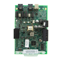
Provides an overview of technical specifications and board layout.
Details the DC power input requirements and specifications for TB1.
Covers EIA-485 serial interface and earth ground connections.
Details telephone line connections, company rights, and Canadian application notes.
Visual representation and explanation of the UDACT-2 board layout.
Overview of UDACT-2 installation compatibility and options.
Step-by-step guide for mounting the UDACT-2 in the NFS-320 chassis.
Procedure for mounting UDACT-2 in the NFS2-640 chassis.
Procedures for mounting UDACT-2 in CHS-M2 and CHS-4 chassis.
Procedure for mounting UDACT-2 in the CHS-4L chassis.
Procedure for mounting UDACT-2 in the CA-1 chassis.
Procedure for mounting UDACT-2 in the CA-2 chassis.
Procedure for mounting UDACT-2 in the CHS-M3 chassis.
Procedure for mounting UDACT-2 on a BMP-1 blank module plate.
General guidance for remote installation of the UDACT-2 unit.
Procedure for installing UDACT-2 in an ABS-8RB enclosure.
Procedure for installing UDACT-2 in UBS-1B/R enclosures.
| Category | Transmitter |
|---|---|
| Type | Digital Alarm Communicator Transmitter |
| Manufacturer | Honeywell NOTIFIER |
| Model | UDACT-2 |
| Compatibility | Compatible with NOTIFIER fire alarm control panels |
| Transmission Format | Contact ID, SIA |
| Operating Voltage | 24 VDC |
| Operating Temperature | 32°F to 120°F (0°C to 49°C) |
| Humidity Range | 10% to 93% non-condensing |
| Communication Protocol | Contact ID, SIA |
| Certifications | UL, FM |
| Operating Current | Standby: 50 mA, Alarm: 150 mA |