EasyManua.ls Logo

Honeywell 5834-4 Series - User Manual

Honeywell 5834-4 Series
2 pages
Print Icon
To Next Page IconTo Next Page
Loading...
5834-4 Series
Wireless Key Transmitter
INSTALLATION AND SETUP GUIDE
GENERAL INFORMATION
The 5834-4 key transmitter is a portable wireless transmitter for use only with wireless alarm systems that support 5800 Series receivers
(ex. VISTA series, LYNX PLUS, LYNX Touch).
Buttons are typically used for arming and disarming, but can be
programmed for any appropriate zone response.
A button must be pressed and held until the LED begins to flash
to activate a button function. This press and hold feature
minimizes the possibility of accidental transmissions.
The factory-installed replaceable lithium battery provides power
for up to five (5) years.
The 5834-4 transmitter provides up to eight (8) functions and has
an optional high security (encrypted) mode that sends rolling-
code encrypted messaging to the RF receiver.
High Security Mode Note: If used in high security mode, must
be used with a receiver or control that supports high security
mode. i.e., 5881EN, 5883, 6150RF, or 6160RF receiver or
LYNXR Series control panel (Rev 13.1 or higher).
PROGRAMMING
For complete details on how to program the transmitter at the control panel, see the control unit's Installation Instructions. When
programming, note the following:
Each 5834-4 transmitter has two unique serial numbers assigned
during manufacture.
Each button on the unit also has a distinct "loop" number (refer to the
Loop Number diagram at right) that you must program into the control
panel during installation.
Assign each button to an individual zone and designate the Input Type
as "BR" (Button Type).
When prompted for the serial number, press and release the
appropriate button(s) twice, or, manually enter the serial number at the
keypad.
NOTE: Serial #2 is one (1) digit higher than serial #1, which is printed
on the rear of the transmitter.
USING HIGH-SECURITY MODE
If used with LYNXR Series controls earlier than Revision
13.1, Standard Mode must be selected.
To use High Security mode, first select High Security mode, then activate
it. Activation syncs the keyfob with the security system.
1. Select High Security mode:
Mode Simultaneously hold down for 5 secs…
High-Security
A - C - D (LED flashes Red when transmitting)
Standard
B - C - D (LED flashes Green when transmitting)
2. Activate High Security Mode: Put the security system into Go/No Go
Mode, then press the appropriate set of buttons as follows:
Serial Number Simultaneously hold down until beeps sound…
1
A - B - C buttons (system beeps twice to confirm)
2
A - B - D buttons (system beeps twice to confirm)
Loop Numbers for the 5834-4 Keyfob Buttons
5834-008-V1
SERIAL #1
LOOP 4
SERIAL #1
LOOP 1
SERIAL #2
LOOP 1
SERIAL #2
LOOP 3
SERIAL #1
LOOP 3
SERIAL #2
LOOP 4
SERIAL #1
LOOP 2
SERIAL #1 FUNCTIONS ACTIVATE WHEN THE RESPECTIVE
BUTTON IS HELD DOWN UNTIL THE LED FLASHES.
SERIAL #2 FUNCTIONS ACTIVATE WHEN THE TWO RESPECTIVE
SERIAL #2 BUTTONS ARE PRESSED AT THE SAME TIME AND
HELD DOWN UNTIL THE LED FLASHES.
NOTE
1.
2.
SERIAL #2
LOOP 2
A
C
B
D
Using a Button: To activate a programmed function,
press and hold the appropriate key(s) until the LED
begins to flash.
ASSIGNING A WIRELESS KEY TO A USER
On most control panels, if the wireless key is assigned to arm and disarm the system, you must assign it to a user in order for it to
operate. This is accomplished through User Code programming at the control panel. See the control panel’s Installation and Setup
Guide for specific instructions on programming User Codes.
The table below summarizes the procedures.
If programming arming and disarming functions on both serial numbers, each serial number must be assigned to a separate user.
On Vista 32/40/50/50P/100 and up
You must assign a user to the button in order for it to operate.
To assign a user number to the Arm/Disarm button:
1. Enter [4-digit User Code] + [8] + [User No.] + [new User Code].
2. Answer Yes or No to the “Open/Close Report ?” question.
3. Answer Yes to the “RF Button ?” question.
4. Enter the zone number assigned to the button.
5. Keypad display shows summary of user information.
6. Test all functions for proper operation.
On Vista-20P/15P/10P/Vista-21iP and variants
You must assign a user to the button in order for it to operate, and
must enter a sequence of keystrokes as described below.
NOTE: There is a two-second timeout for keystroke commands on
Vista P series panels, therefore you must enter the keystrokes as
quickly as possible.
1. Enter [4-digit Master Code] + [8] + [User Number] +
[# 4] + [two digit zone number] assigned to the fob.
2. Test all functions for proper operation.
Question and Answer IconNeed help?

Do you have a question about the Honeywell 5834-4 Series and is the answer not in the manual?

Summary

Honeywell 5834-4 Series Wireless Key Transmitter

General Information and Features

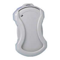
Portable wireless transmitter for alarm systems, features arming/disarming, long battery life, and minimizes accidental transmissions.

Programming the 5834-4 Key Transmitter

Transmitter Programming Basics

Program each button to a zone with Input Type 'BR'. Enter serial number or press button twice.

Serial Number Assignment Note

Serial #2 is one digit higher than serial #1 printed on the transmitter.

Using High-Security Mode

Selecting High Security Mode

Simultaneously hold down specific buttons for 5 seconds to select mode.

Activating High Security Mode

Put system in Go/No Go mode, then press specific buttons until beeps sound.

Assigning a Wireless Key to a User

User Assignment for Vista 32;40;50;50 P;100

Assign user to button via User Code programming, answer 'RF Button?' Yes, enter zone number.

User Assignment for Vista-20 P;15 P;10 P

Assign user to button by entering Master Code + 8 + User No. + #4 + zone number.

Battery Information and Replacement

Battery Replacement Procedure

Remove screw, pry out old battery, insert new battery with positive end up, secure case.

Battery Life and Performance

Battery life varies; ambient conditions affect it. Low battery reported as trouble. Test regularly.

Safety Disclaimer

Wireless key is for convenience, not life safety. Select supervised key for life safety needs.

Specifications and Warranty

Device Specifications

Unit dimensions: 2.25" x 1.25" x 0.5". Battery: 3V, 210mAh.

Warranty Details

Refer to website for the latest warranty information.

Federal Communications Commission Statements

FCC Compliance and User Modifications

User must not modify equipment. Unauthorized changes void authority to operate.

FCC Notice Requirements

Device complies with FCC rules, subject to two conditions to avoid interference.

Overview

The Honeywell 5834-4 Series Wireless Key Transmitter is a portable wireless device designed for use with wireless alarm systems that support 5800 Series receivers, such as VISTA series, LYNX PLUS, and LYNX Touch systems. It serves primarily for arming and disarming security systems, but its buttons can be programmed for various other zone responses.

Function Description

The 5834-4 transmitter provides up to eight distinct functions. A key feature is its optional high-security (encrypted) mode, which sends rolling-code encrypted messages to the RF receiver, enhancing security. To activate a button function, the user must press and hold the button until the LED begins to flash. This "press and hold" feature is incorporated to minimize the possibility of accidental transmissions, ensuring that commands are intentional.

Important Technical Specifications

  • Dimensions: The unit measures 2.25" x 1.25" x 0.5" (57mm x 31.75mm x 12.7mm), making it compact and portable.
  • Battery: It operates on a 3V, 210mAh lithium battery (Maxell CR2032 or Duracell DL2032). The factory-installed battery is designed to provide power for up to five years under normal conditions.
  • Serial Numbers and Loops: Each 5834-4 transmitter has two unique serial numbers assigned during manufacturing. Additionally, each button on the unit has a distinct "loop" number that must be programmed into the control panel during installation. These loop numbers define which button corresponds to which function.
    • Serial #1 Functions: These activate when the respective button is held down until the LED flashes.
      • Loop 1: Button D
      • Loop 2: Button B
      • Loop 3: Button A
      • Loop 4: Button C
    • Serial #2 Functions: These activate when two respective Serial #2 buttons are pressed simultaneously and held down until the LED flashes.
      • Loop 1: Buttons A and B
      • Loop 2: Buttons C and D
      • Loop 3: Buttons A and C
      • Loop 4: Buttons B and D
  • Input Type: When programming, each button should be assigned to an individual zone and designated with an "BR" (Button Type) input type.
  • High Security Mode Compatibility: If used in high-security mode, the transmitter must be paired with a receiver or control panel that supports this mode, such as 5881EN, 5883, 6150RF, 6160RF receivers, or LYNXR Series control panels (Revision 13.1 or higher). For LYNXR Series controls earlier than Revision 13.1, Standard Mode must be selected.

Usage Features

  • Programming: The transmitter's buttons can be programmed for various functions beyond arming and disarming. During programming, when prompted for the serial number, users can either press and release the appropriate button(s) twice or manually enter the serial number at the keypad. Serial #2 is always one digit higher than Serial #1, which is printed on the rear of the transmitter.
  • High-Security Mode Activation: To use High Security mode, it must first be selected and then activated.
    • Selection: Simultaneously hold down buttons A, C, and D for 5 seconds until the LED flashes Red when transmitting. For Standard Mode, hold down B, C, and D until the LED flashes Green.
    • Activation: Put the security system into Go/No Go Mode. For Serial Number 1, simultaneously hold down buttons A, B, and C until the system beeps twice to confirm. For Serial Number 2, simultaneously hold down buttons A, B, and D until the system beeps twice to confirm. This process syncs the keyfob with the security system.
  • User Assignment: On most control panels, if the wireless key is used for arming and disarming, it must be assigned to a user through User Code programming. Each serial number (if programming arming/disarming functions on both) must be assigned to a separate user.
    • Vista 32/40/50/50P/100 and up: To assign a user, enter [4-digit User Code] + [8] + [User No.] + [new User Code], answer "Yes" to "Open/Close Report?" and "RF Button?" questions, then enter the zone number assigned to the button.
    • Vista-20P/15P/10P/Vista-21iP and variants: To assign a user, enter [4-digit Master Code] + [8] + [User Number] + [#4] + [two-digit zone number] assigned to the fob. Keystrokes must be entered quickly due to a two-second timeout.

Maintenance Features

  • Battery Replacement: The LED will not flash during transmission if the battery is low, and the device will report a low battery condition to the control panel as a trouble condition when a button is pressed.
    • To replace the battery: Remove the screw from the case back. Insert a small screwdriver under the battery and twist to release it. Insert a new 3V CR2032 lithium battery (Maxell or Duracell) with the positive (+) end facing UP, sliding it under the gold tab, then pressing down to snap into place. Replace the case back and screw. It is crucial not to remove the printed circuit board.
  • Battery Life: While designed for several years of battery life under normal conditions, environmental factors like high humidity, extreme temperatures, or large temperature fluctuations can reduce the expected battery life. Regular testing and maintenance are recommended to ensure the system remains in good operating condition.
  • Safety Note: This wireless key is intended as a convenience and should not be considered a life safety device. For life safety applications, a supervised wireless key (e.g., type 5802MN) should be selected.

Regulatory Compliance

The device complies with Part 15 of FCC Rules and RSS 210 of IC. Operation is subject to two conditions: it may not cause harmful interference, and it must accept any interference received, including interference that may cause undesired operation. Any unauthorized changes or modifications to the equipment could void the user's authority to operate it.

Honeywell 5834-4 Series Specifications

General IconGeneral
BrandHoneywell
Model5834-4 Series
CategoryTransmitter
LanguageEnglish

Related product manuals