104 UDACT Instruction Manual — P/N 50050:M 12/18/2009
AM2020/AFP1010 (UL 8th) Wiring
H.3.2 Notes
1. Ferrite cores, PN 29090, are recommended for all applications.
2. Recommended wire is 12 AWG (3.25mm
2
) to 18 AWG (0.75mm
2
), twisted pair, shielded
cable. Connect only one end of shield: a) shield may be connected to cabinet (earth ground) at
fire alarm panel, or b) shield may be connected to TB1 Terminal 5 (Shield) at UDACT as
shown in Figure H.1.
3. Conduit is recommended for external wire runs. Consult local building codes.
4. Refer to "Specifications" on page 13 for power requirements.
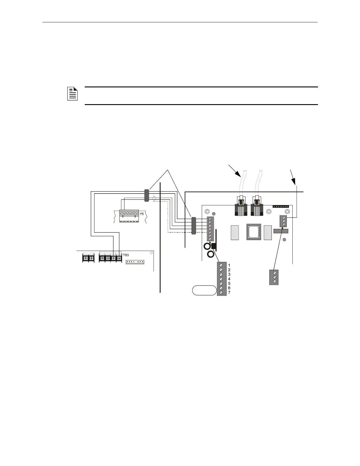
Below is a remote installation of a UDACT with an AM2020/AFP1010using an MPS-24A main
power supply:
Figure H.1 UDACT and AM2020/AFP1010 with MPS-24A
NOTE: The shield end that is not connected should be insulated to prevent accidental grounding.
Do not connect both ends of shield under any circumstance since a ground fault may result.
EARTH
Comm FAILURE
+24V
+24V
GND
RS+
RS–
SHIELD
RS+
Rs–
ACS/TERM
TERM
+24R COMMO N + 24
COMMON
POWER LIMI TED
BAT + B AT -
To Phone Lines
(supervised)
Solid Earth
Ground
Connection
MPS-24A
SIB-2048
EIA-485
Interface
DO NOT USE
UDACT-15.cdr
CAB-3/4 Series Cabinet
Ferrite Cores
ABS-8RB or UBS-1

 Loading...