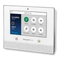
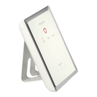
Lyric Controller Installation and Reference Guide
- 10 -
Installing
InstallingInstalling
Installing
the Control
the Control the Control
the Control (Continued)
AC Power
AC PowerAC Power
AC Power
The Lyric Controller is powered by a 110VAC, 60 Hz/9 Volt DC, 2.5 Amp Plug-in Power Supply, 300-04705V1
(300-04063V1 in Canada). Refer to the wiring table below for wire gauge and length.
WIRING TABLE
WIRING TABLEWIRING TABLE
WIRING TABLE
MAXIMUM DISTANCE BETWEEN POWER
MAXIMUM DISTANCE BETWEEN POWER MAXIMUM DISTANCE BETWEEN POWER
MAXIMUM DISTANCE BETWEEN POWER
SUPPLY AND CONTROLLER
SUPPLY AND CONTROLLERSUPPLY AND CONTROLLER
SUPPLY AND CONTROLLER
GAUGE
GAUGEGAUGE
GAUGE
Use only the 300
Use only the 300Use only the 300
Use only the 300-
--
-04705V1
04705V1 04705V1
04705V1
(300
(300(300
(300-
--
-04063V1
04063V1 04063V1
04063V1
Canada) Po
Canada) PoCanada) Po
Canada) Power Supply. Do not plug the
wer Supply. Do not plug the wer Supply. Do not plug the
wer Supply. Do not plug the
power supply into the AC outlet until after
power supply into the AC outlet until after power supply into the AC outlet until after
power supply into the AC outlet until after
all wiring connections have been made
all wiring connections have been madeall wiring connections have been made
all wiring connections have been made.
..
.
Wiring Overview
Wiring OverviewWiring Overview
Wiring Overview
The following summarizes the electrical connections associated with the Lyric Controller. Follow the steps and
refer to the figure below when making connections. Refer to the Summary of Connections diagram for
additional information.
Make Electrical Connections
Make Electrical ConnectionsMake Electrical Connections
Make Electrical Connections
1. Temporarily hang the controller from the hook on the wall mount.
2. If used, connect the hardwire sensors/contacts to the HWZ1/HWZ2 (+) and GND (-) terminals.
3. Remove the Power Supply Sleeve from the Power Supply.
4. Route the wiring through the Power Supply Sleeve (if used).
5. Connect the wires to the +9VDC and GND terminals on the Power Supply and reinstall the Sleeve.
6. Align the slots on the back of the controller with the hooks on the wall mount as shown below.
7. Once attached, insert the screw to secure the controller to the wall mount.
8. Plug the power supply into a 24-hour, 110VAC unswitched outlet. Upon power-up, the “System Standby!”
screen will be displayed.
lyric-035-V1
USB PORT
DETAIL A
BATTERY
RECEPTACLE
TAMPER
TERMINAL
BOARD
HWZ2
GND
HWZ1
+9VDC
GND

 Loading...
