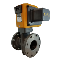
The Honeywell Maxon Oil Electro-mechanical Valves are designed for automatic and manual shut-off applications. These valves are available in normally-closed and normally-open options. The normally-closed versions will shut off flow when de-energized and pass flow when energized. Conversely, the normally-open versions will shut off flow when energized and pass flow when de-energized. Electro-mechanical valves are also offered in configurations that meet hazardous locations.
Function Description
The Maxon Oil Electro-mechanical Valves are designed to control the flow of oil in various industrial applications. They are available in both normally-closed and normally-open configurations, offering flexibility in system design. The valves are actuated by an electric motor, which drives the valve stem to open or close the valve. Auxiliary signal switches are available to provide remote indication of valve position.
Important Technical Specifications
The valves are designed for a maximum operating pressure (M.O.P.) suitable for the intended application. The maximum operating temperature (T_OP) and ambient temperature range (T_AMB) are specified to ensure proper operation within environmental limits. The fluid temperature range (T_F) indicates the acceptable temperature range of the media flowing through the valve.
The valves are available with various solenoid/clutch voltage and frequency options. The motor voltage and frequency are also specified.
Auxiliary signal switches are available in different configurations:
- SPDT (HS): Single pole double throw hermetically-sealed switch(es)
- SPDT: Single pole double throw switch(es)
- SPDT (HC): Single pole double throw high capacity switch(es) (used when DC motors are ordered)
- DPDT: Double pole double throw switch(es)
The valve position indicators include:
- VOS-1/2: Valve open switch(es)
- VCS-1/2: Valve closed switch(es): proof of closure
The valves are designed for continuous duty and are suitable for installation in Class I, Division 2, Groups B, C, D and Class II Groups F and G, and Class III hazardous locations or non-hazardous locations (applies to 4700NI valves only).
Usage Features
The Maxon Oil Electro-mechanical Valves are designed for ease of installation and operation. The instruction manual provides detailed guidance on mounting, wiring, and commissioning.
- Installation: The valves can be mounted in any position, but for optimal performance, horizontal piping with the valve stem in a horizontal position is recommended. The valve side plates should be filled in vertical plane for best performance. Valves are usually installed in horizontal piping; however, other positions are acceptable, subject to the above limitations. All top assemblies of all MAXON valves are field rotatable to allow installation, avoiding conflicts with piping mounting restrictions.
- Wiring: All wiring must conform to the NEC/ANSI/NFPA 70 and/or CSA C22.2 No. 1. Supply voltages must agree with valve's nameplate voltage within -15%/+10% for proper operation. For electrical wiring schematic, see instructions or sample affixed inside valve terminal block cover. Grounding is achieved with a grounding screw, which is located in the top assembly. Customer connections are provided via terminal blocks located in the top assembly. Main power wiring (120 VAC or 240 VAC) must be segregated from lower voltage 24 VDC signal wiring when both are required. To eliminate any potential for gas to enter the electrical wiring system, install a conduit seal fitting at the actuator conduit hub.
- Auxiliary Switches: The valves can be equipped with internally-mounted signal switches to provide "proof-of-open" or "proof-of-closed" valve position indication. Auxiliary signal switches indicate when the valve is open or closed and are normally connected electrically into your control panel lights or warning device circuit(s). VOS (Valve Open Switch) is actuated when the valve is fully open. It is the lower snap-switch mounted on front of switch bracket. VCS-1 is an SPDT (single-pole, double-throw) switch. All contacts are available for external circuitry. VOS (Valve Open Switch) is actuated when the valve reaches full-open. It is the lower snap-switch mounted on front of switch bracket. VCS-1 is an SPDT switch. On automatic reset valves, the normally closed contact serves as a motor limit switch and is not available for external circuitry. VOS-2 is DPDT, used in lieu of VOS-1 for additional contacts.
- Operating Environment: Actuators are rated for NEMA 4 or optional NEMA 4X. Ambient and fluid temperature range of -20°F to +140°F for 3/8 & 1 1/4" valves. Ambient and fluid temperature range of -20°F to +125°F for 3/8", 1/2", 3/4" valves. All valves for oxygen service or using Ethylene Propylene body seals are limited to a minimum ambient and fluid temperature of 0°F.
- Hazard Warnings: Proper installation and operation are crucial for safety. Do not connect or disconnect this equipment unless power has been removed or the area is known to be non-hazardous. Substitution of components may impair suitability for Class I, Division 2 (applies to 4700NI valves only). This equipment is suitable for installation in Class I, Division 2 Groups B, C, D and Class II Groups F and G, and Class III hazardous locations or non-hazardous locations (applies to 4700NI valves only).
Maintenance Features
The Maxon Oil Electro-mechanical Valves are designed for long life and are considered free and trouble-free as possible. A valve operational test should be performed on an annual basis. If abnormal opening or closing is observed, the valve should be removed from service and your MAXON representative should be contacted.
- General Maintenance and Spare Parts: All safety devices should be tested at least monthly. Periodically for tightness, motorized shut-off valve closure is equally essential. Only items shown as suggested spare parts are considered field replaceable.
- Component Identification: To determine suggested spare parts, identify series designation and serial number from the valve nameplate. Refer to the illustration and legend below to identify suggested spare parts.
- Actuator Assembly Rotation: The actuator assembly can be rotated to 90° increments around the valve body centerline axis using the procedure below. This allows for flexibility in installation and maintenance.
- Field Installation of Valve Position Switch: The valve position switch can be installed in the field to provide remote indication of valve position.
- Warning: Do not attempt field repair of valve body or actuator. Any alterations void all warranties and can create potentially hazardous situations. If foreign materials or corrosive substances are present in the fuel line, it will be necessary to remove the valve to make certain it is operating properly. If abnormal opening or closing is observed, the valve should be removed from service. Contact your MAXON representative for instructions. Operator should be aware of and observe characteristic opening/closing action of the valve. Should operation ever become sluggish, remove valve from service and contact MAXON for recommendations.
- Address Inquiries: Address inquiries to MAXON. Local worldwide offices may be located at www.maxoncorp.com. Include valve serial number and nameplate information.