GAS ELECTRO-MECHANICAL VALVES
E - m - 05/22 3 32M-95001—04
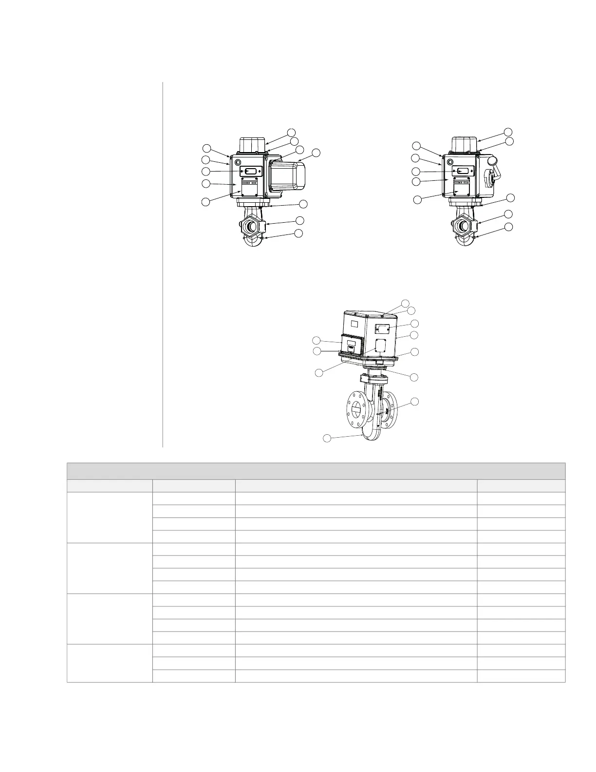
Component identification
1) Access cover screws
2) Access cover
3) Visual indication
4) Mainbase
5) Nameplate
6) Actuator bolts
7) Flow arrow
8) Valve body
9) Terminal block cover
screws
10) Terminal block cover
11) Motor cover screws
12) Motor cover
13) Top cover plate
screws
14) Top cover plate
15) Top housing
16) Top housing screws
Automatic (motorized) valve
Model designation
SMA11, CMA11, SMA21, CMA21
Manual valve
Model designation
SMM11, CMM11, SMM21
Automatic (motorized) valve - high capacity
Model designation
HMA11
Table 1 - Torque specifications
Valve type Item number Description Torque N.m
“S” Valves
DN20 - DN40
(3/4” - 1-1/2”)
1 Access cover screws 1/4-20 8.1 N.m
6 Actuator bolts 5/16-18 18 N.m
9 Terminal block cover screws 1/4-20 8.1 N.m
11 Motor cover screws #10-24 4.7 N.m
“S” Valves
DN50 - DN80
(2” - 3”)
1 Access cover screws 1/4-20 8.1 N.m
6 Actuator bolts 3/8 - 16 27 N.m
9 Terminal block cover screws 1/4-20 8.1 N.m
11 Motor cover screws #10-24 4.7 N.m
“C” Valves
DN50 - DN100
(2” - 4”)
1 Access cover screws 1/4-20 8.1 N.m
6 Actuator bolts 3/8 - 16 27 N.m
9 Terminal block cover screws 1/4-20 8.1 N.m
11 Motor cover screws #10-24 4.7 N.m
“H” Valves
DN100 - DN150
(4” - 6”)
9 Terminal block cover screws #10-24 4.7 N.m
13 Top cover plate screws 1/4-20 8.1 N.m
16 Top housing screws 1/4-20 8.1 N.m
10
9
6
8
7
1
2
3
4
5
10
9
5
7
3
13
14
15
16
6
8
 Loading...


