Document 800-07475V3 – Rev A – 10/2011
MAXPRO
®
NVR SE Series Quick Install Guide
See over for the next step.
Overview
This document covers how to:
• Connect essential hardware to a MAXPRO NVR SE unit.
• Configure network settings, set up IP addresses, and discover connected devices.
• Configure the unit to record video.
Note More detailed MAXPRO NVR SE documentation is available on the Documentation DVD included with
your unit.
1 Before You Begin
The following items come with your MAXPRO NVR SE chassis and may be needed for installation and setup:
Minimum Hardware Requirements
Make sure your workstations meet the following minimum hardware requirements. Note that workstations are only
required if you have remote NVR clients in your system.
2 Installing Unit
Components of a MAXPRO NVR SE System
Your system may include some or all of the following components:
• Optional hard drives for additional storage (included if ordered)
• One or many video cameras and/or PTZ domes (owner supplied)
• A VGA monitor (owner supplied)
• A keyboard controller (owner supplied)
• A computer keyboard (included)
• A computer mouse (included)
• One Rail hardware kit for rack mount installations (included)
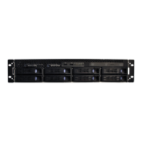
Mounting the MAXPRO NVR Unit in a Rack
1. Remove the bezel from the front of the unit. Turn the two bezel key locks clockwise to loosen, then pull away from
the unit.
2. The MAXPRO NVR SE unit should be mounted with the supplied Rail hardware kit. The rail kit allows you to slide
the MAXPRO NVR SE unit in and out of the rack it is mounted into and provides rear support for the chassis. Refer
to the instructions included with the Rail hardware kit when installing the unit with the Rail kit.
3. To replace the front bezel, align the bezel key locks with the handles on the front plate of the unit and then slide
the front bezel into place. Turn the bezel key locks counterclockwise to secure.
3 Connecting Hardware
Rear Panel Connections
•Power cord
• Keyboard (PS/2)
•Mouse (PS/2)
• DVI and VGA cable adapters
•This Quick Install Guide
• Recovery DVD
• Rail hardware kit with instructions
for rack mount installations
• Optional, additional hard drive(s)
• 8 or more screws for hard drive
installation
• MAXPRO NVR SE Software and
Documentation DVD
Note Other peripheral hardware (owner supplied) will also be needed for your installation (such as cameras, network
equipment and an optional keyboard controller). See 2 Installing Unit, for more information.
Specification MAXPRO NVR Workstation
Processor Intel
®
Core™ 2 Duo Processor E6750 2.66 GHz or Quad Core Intel
®
Xeon
®
E5405 2.0 GHz (faster speeds are optional)
Operating System Microsoft
®
Windows
®
7 Professional
System Memory (RAM) 4 GB of RAM minimum
DVD Drive DVD-RW drive. An RW (Read Write) drive is required if the workstation is used
for exporting recordings.
Disk Single Disk or RAID 0 or 0+1 10K SATA 80 GB or 10K to 15K SAS 73 GB with
Windows Operating System
Multiple Monitor Card –
Display Adapter
1 x 256 MB PCIe x 16 NVIDIA Quadro NVS 285, Dual DVI or Dual VGA or
DVI+VGA. This is for a two monitor setup with each monitor requiring 128 MB.
Network Connection 1 Gigabit/sec Network Interface Card (NIC) or greater
Video Resolution 1280 x 1024 pixels (resolution), 65K colors non-interlaced (color quality). Please
refer to the MAXPRO
®
NVR Commissioning and Installation Guide for more
information on configuring monitor properties.
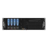
Bezel key lock (x2)
Hard drive release button.
The first drive is the one on the right. They are
numbered 1 to 4, from right to left.
ACT/LNK
HDMI
10 = OFF
100 = GRN
1000 = YLW
# Connector Connects to...
1 Power Electrical outlet
2 DMS-59 Pin PC video card
3 DIN-8 Connector PC PS/2 Mouse
4 DIN-8 Connector PC PS/2 Keyboard
5 DB-15 VGA Connector Monitor
6 HDMI Monitor
7 S/PDIF Out Interface Audio In on device
8 USB Ports Various devices
8
11–16
2
# Connector Connects to...
9 Gigabit LAN 1- Camera Network Port Network
10 Gigabit LAN 2 - Client Network Port Network
11 Audio output (gray) Side surround
12 Audio output (black) Back surround
13 Audio output (orange) Subwoofer
14 Audio input (red) Microphone in
15 Audio output (green Front)
16 Audio input (blue) Line-in
3
5
1
4
10
9
7
6
2nd NIC card is optional. It must
be ordered separately and field
installed.
Camera(s)
Connect a network switch to the Gigabit LAN 1 connector at the rear of the MAXPRO NVR SE unit. Connect your
cameras either to the network switcher or to other Ethernet network connections in your system with CAT5 Ethernet
cables.
Monitor(s)
The MAXPRO NVR SE comes with a dual graphics card, so two monitors can be connected. A DVI monitor is best-
suited for viewing live video. Connect the monitor to the supplied DMS-59 to dual DVI adapter cable, then connect the
cable to the DMS-59 connector (2) on the rear panel of the unit. Do not use the HDMI (7) or VGA (6) graphics ports as
these are disabled. The recommended settings for your monitor are: 1280 x 1024 pixels (resolution), and 65K colors
non-interlaced (color quality). Refer to the MAXPRO
®
NVR Commissioning and Installation Guide for more information
on configuring the monitor display properties.
Keyboard and Mouse
Before powering up the MAXPRO NVR SE, connect the supplied PS/2 keyboard and mouse to the DIN-8 connectors at
the rear of the unit.
Keyboard Controller
Follow the documentation that was included with your Keyboard Controller to connect it to the MAXPRO NVR SE unit.
4 Powering Up the Unit
Note Honeywell recommends using an uninterruptible power supply (UPS) for the MAXPRO NVR SE unit and
the cameras. Powering the cameras and unit from a UPS ensures that the MAXPRO NVR SE unit can
continue to record video during a power outage. If you need to monitor video during a power outage,
consider a UPS for the monitor as well.
MAXPRO NVR SE Power Up Sequence
1. Turn on camera(s) and other hardware connected to the MAXPRO NVR SE unit.
Note Honeywell recommends that cameras be powered on before the MAXPRO NVR SE unit starts up. It can
take up to two minutes for IP cameras to boot up. Online cameras can be easily discovered by the unit after
starting up. It is also recommended to turn on other associated network components such as a network
switch or router before the MAXPRO NVR SE starts up.
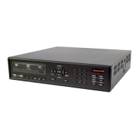
2. Press and hold the power button on the front of the MAXPRO NVR SE unit (the power button is labelled 9 in the
image below). The power button turns blue after the unit is powered up.
3. After powering up, you are prompted to log on. The Default user is user name: Administrator, password:
Password1. The user name and password are case sensitive.
Front Panel LEDs
12
HCD554IP
HD3MDIP
HD4DIP
MAXPRO NVR SE
Client Workstation
DVI/VGA
DVI/VGA
CAT5e
CAT5e
CAT5e
CAT5eCAT5e
Network Switch PoE
No. LEDs, Buttons Color Behavior
1 Fan fail LED Red On = The system detects a fan abnormality.
Off = The fan is operating normally.
2 Temperature LED Red On = The system temperature exceeds the maximum threshold.
Off = The system temperature is within normal range.
3 Power LED Blue On = The system is powered on.
Off = The system is powered off.
4 Buzzer LED Red On = The buzzer is on mute.
Off = The buzzer sounds.
5 HDD LED Blue On = There is hard drive activity.
6 NIC1 LED Yellow On = There is network activity.
7 NIC2 LED Yellow Always off; not supported.
8 Alarm LED Green On = When certain active components fail or the threshold is exceeded.
Off = Normal operation.
9 Power button Red Push to power on the unit.
10 Reset button Red Push to reset the unit.
11 HDD Activity/Ready
LED
Blue On = Hard drive is inserted and detected.
Flash = System is accessing the hard drive.
Off = There is no hard drive or it is not detected.
HDD Failure LED Red On = The hard drive is detected as a failure by the host.
Flash = RAID rebuilding.
Off = There is no hard drive or it is operating normally.