43
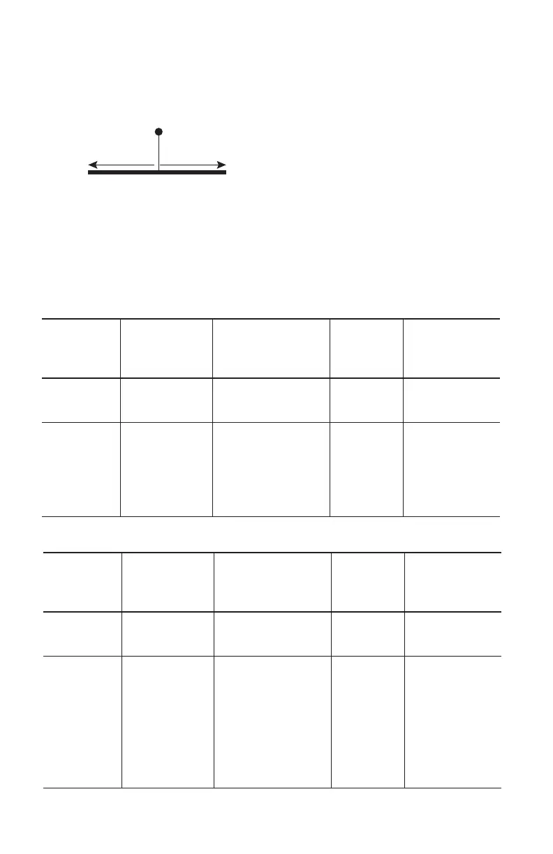
Diagram 2 - OVERHEAD VIEW OF LEADING EDGE APPLICATION /
Diagramme 2 - VUE AÉRIENNE DE L’APPLICATION POUR LES BORDS COUPANTS /
Diagrama 2 - VISTA EN ALTURA DE LA APLICACIÓN DE BORDE AFILADO
Refer to ‘Fall Clearance Tables for Leading Edge Applications’ (work zone limitations).
Reportez-vous aux tableaux de dégagement de chute pour les applications pour les
bords coupants (limitations de la zone de travail).
Consulte las “Tablas de distancia de caída para aplicaciones de bordes afilados” (limita-
ciones de la zona de trabajo).
Anchor Point
Edge
≤6 ft
(1.8m)
≤6 ft
(1.8m)
/ Point d’ancrage / Punto de Anclaje
/ Bord / Borde
TABLE 1: Minimum Set-Back Distance Anchorage Requirements for Leading Edge (LE)
Approved
Edges
Lifeline Material
Approved
for
Tie-Back
Installation
Minimum
Set-Back
Distance
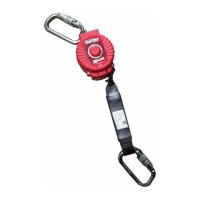
TurboLite+
SHARP EDGE
Radius ≥ .005 in
(.13mm)
Galvanized Cable NO None
TurboLite+
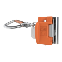
T-BAK
SHARP EDGE
Radius ≥ .005 in
(.13mm)
Galvanized Cable
(with Heavy-Duty
Vectran/Polyester
Webbing portion for
tie-back installation)
YES
Varies - Set-back
distance must
ensure that web-
bing portion of the
lifeline shall not
contact an edge
during a fall.
TABLEAU 1: Exigences minimales d’ancrage pourles bords coupants (LE)
Approved
Edges
Lifeline Material
Approved
for
Tie-Back
Installation
Minimum
Set-Back
Distance
TurboLite+
SHARP EDGE
Rayon ≥ 0.005
po (0.13 mm)
Câble galvanisé NON Aucun
TurboLite+
T-BAK
SHARP EDGE
Rayon ≥ 0,005
po (0.13 mm)
Câble galvanisé (avec
partie de sangle en
Vectran/polyester ro-
buste pour l’installation
tie-back)
OUI
Varie - La
distance de recul
doit être calculée
de sorte que
la portion de la
enrouleur à rappel
ne doive pas
entrer en contact
avec un rebord
lors d’une chute.
 Loading...