35 AND 70 LB-IN. NON-SPRING RETURN DIRECT COUPLED ACTUATORS
9 63-2209—8
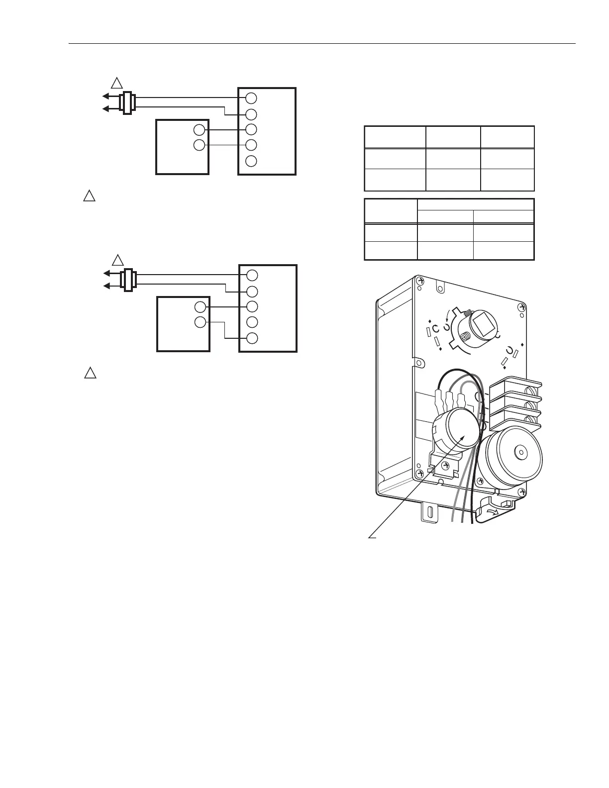
Fig. 13. ML7161 or ML7174 used with 2-10 Vdc control.
Fig. 14. ML7161 or ML7174 used with 4-20 mA control.
Auxiliary Switches
The 201052A or B Auxiliary Switch is used in conjunction with
the actuator. It allows for control of equipment external to the
actuator (for example, electric reheat coils and fan) at an
adjustable point in the stroke (0° to 90°) of the actuator.
The 201052A and B Auxiliary Switches are field-addable. For
mounting instructions, see form 63-2218, provided with the
device.
IMPORTANT
When operating an ML6161 or ML6174 from a two-
position controller, a 201052B Auxiliary Switch is
required for proper operation. See Fig. 12.
Auxiliary Potentiometers
The 200976A,C Auxiliary Potentiometers mount on the face of
the ML6161A,C or ML6174A,C (as shown in Fig. 15). The
potentiometer shaft has a slipping collar. If one of the two
limits of the potentiometer is exceeded, the collar continues to
rotate, causing no damage to the potentiometer itself. To
mount the potentiometer on the actuator:
1. Turn the potentiometer to align the shaft key with the
slot in the potentiometer drive.
2. Tilt the potentiometer slightly so the key faces down
toward the slot.
3. Insert the potentiometer into the slot, and push down so
the potentiometer is flush with the actuator body and the
bracket is aligned over the screw hole.
4. Insert the screw provided into the hole and fasten
securely.
IMPORTANT
Failure to follow the calibration procedures can result
in improper resistance values at desired stroke.
Fig. 15. ML6161A,C, ML6174A,C with
field-addable potentiometer.
To Calibrate the 200976A,C:
IMPORTANT
Remove the range stop pins and minimum position
setscrews prior to calibration.
1. Drive the actuator fully closed (0°) to fully open (90°)
and back again to the fully closed position. This must be
done to receive the correct resistance readings at the
appropriate degree of stroke.
2. Check the resistance values of the potentiometer with
an ohmmeter at intervals in the stroke while referring to
the table in Fig. 15 and resistance information provided
in the Specifications section.
3. Replace the range stop pins and/or the minimum
position setscrews using the appropriate procedures.
L1
(HOT)
L2
1
1
POWER SUPPLY. PROVIDE DISCONNECT MEANS AND OVERLOAD
PROTECTION AS REQUIRED.
4-20 mA CONTROLLER
ML7161, ML7174
T1
T2
–
–
+
+ mA
+ V
M18071
L1
(HOT)
L2
1
1
POWER SUPPLY. PROVIDE DISCONNECT MEANS AND OVERLOAD
PROTECTION AS REQUIRED.
2-10 Vdc CONTROLLER
ML7161, ML7174
T1
T2
–
–
+
+ mA
+ V
M18072
60
45
45
60
CW
CCW
COM
M10251B
MOTOR
POSITION
RW
RESISTANCE
RB
RESISTANCE
FULLY CW
24V (COM-CW)
FULLY CCW
24V (COM-CCW)
0 OHMS
0 OHMS
500 OR
2000 OHMS
AUXILIARY POTENTIOMETER
MOTOR
ROTATION
AUXILIARY POTENTIOMETER LEADS
RW OHMS RB OHMS
CCW
INCREASE
DECREASE
DECREASE
INCREASE
CW
FIELD-ADDABLE AUXILIARY POTENTIOMETER
500 OR
2000 OHMS
B
R
W
 Loading...


