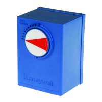
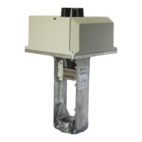
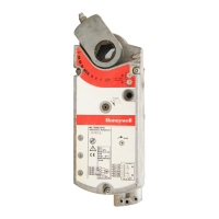
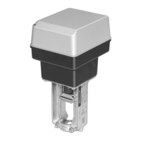
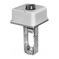
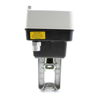
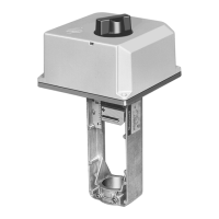
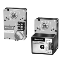
ML6984, ML7984 DIRECT COUPLED VALVE ACTUATORS
ML6984 Operation
The motor is controlled by a microprocessor.
Connecting B to R tells the microprocessor to cause the
actuator to drive open. Connecting W & R for one second
or longer will cause the actuator to drive closed. For
“floating” control, if R remains open, the actuator will
remain in the last position.
At the end of the valve stroke, the actuator will develop
the necessary force for positive valve close-off.
As forces are developed, the current to the motor
increases. The microprocessor stops the actuator
automatically when the motor current, and forces reach
the predetermined level.
ML6984 does not need to be powered on terminals
T5-T6, but self-calibration will not occur. The controller
must drive the valve through a cycle to calibrate stroke
length. Input signals lasting over 3 1/2 minutes will be
ignored until the switch cycles off to avoid a motor stall
condition.
1. Disconnect power supply before beginning installation
to prevent electrical shock and equipment damage.
2. All wiring must comply with applicable local electrical
codes, ordinances and regulations.
3. Make certain that the voltage and frequency of the
power supply correspond to the rating of the device.
4. DO NOT electrically operate the ML_984 actuator
before assembly to the valve because damage not
apparent to the in staller may occur.
5. DO NOT connect 24 Vac between any ML7984 signal
input terminals. DEVICE FAILURE WILL RESULT!
REPLACEMENT NOTES
To replace ML684
1. The new ML6984 is a direct replacement for the
old ML684A in single actuator or parallel multiple
actuators hook-up. The old and new actuators can
be mixed in the same electrical circuit. For multiple
actuators controlled by a common controller in
parallel, these actuators must be wired so that
they all travel in the same direction.
2. When replacing the ML684A1009 (80 lbs ) with
this new ML6984 on the V5045 valve. The already
installed valve adaptor (part # 272629A) on the
valve stem and actuator assembly is still needed.
To replace ML6874
1. The ML6984 is a direct replacement for the old
ML6874 in single actuator hook-up.
2. For parallel multiple old ML6874 actuators
applications, an isolation relay must be used
(isolation relay contacts should be placed in the
new ML6984 actuator signal input “W” and “B”
circuit).
10
ML7984 Operation
The sensing circuits respond to the signal across the
input terminals based on the configuration DIP switch
settings.
When correctly connected to the actuator, control
signal between signal input terminals is converted to a
digital run time and compared to pulse counts from the
first gear in the gear train. When these counts are equal,
the drive motor and drive shaft are stationary.
As long as the value of controlled medium remains at
the controller setpoint, the circuit is in balance, and the
actuator does not run. When the value of the controlled
medium changes, the controller output voltage is
changed causing the counters to differ. As the actuator
moves in the direction to correct the medium change,
the counters increment or decrement, and stop the
actuator when the input and gear counts agree.
At the end of the valve stroke, the actuator develops
the necessary force for positive valve close-off. The motor
stops automatically when the motor current reaches the
predetermined current and force level. The digital
counters are reset and calibrated at each end of stroke.
GENERAL NOTE:
1. The ML7984 must be field configured with the DIP
switches which are located beside the terminal block.
See wiring diagrams for details. Turn power off before
setting the DIP switches .
2. There is a short delay in actuator response upon every
signal change. This is to screen any unwanted
incoming signals.
3. For proper operation, voltage on the T5 and T6 must
not be less than 22 Vac or 24Vdc during running or
force generating stages.
Operation
Each time actuator terminals T5-T6 are (re)powered, the
microprocessor will cycle the valve through a full stroke
to calibrate its position. Any stroke between 1/2” (13 mm)
and 1” (25 mm) will be divided into 30 equal steps. Run
time will be proportional to stroke length. The LED lights
when terminals T5-T6 are powered, and flash when the
actuator is in motion.

 Loading...
