5
ML6984 Wiring
In multiple actuators connection, power supply to all actuators must be connected in a TRUE parallel fashion to reduce
excessive voltage drop. DO NOT “daisy chain” i.e. connected to one actuator then branched to another.
(in all cases when wiring a ML_984 Actuator)
ML_984 actuators are designed to operate from a Safety Extra Low Voltage, Class II power source. A 7/8” wiring hole
is provided for attaching flexible conduit where required by local codes. When installing outdoors, weatherproof conduit
fittings approved for outdoor and wet locations must be used.
Operation
The recommended valve actuator power source is a Safety Extra-Low Voltage (SELV) Class II, 24V transformer or
regulated 28Vdc across terminals T5 & T6. Internal circuitry provides dc power for the electronic sensing and drive
motor circuits.
Wiring
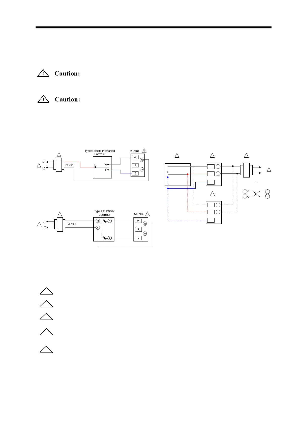
FIG. 7A — 3-WIRE CONTROL OF ML6984 WITH
SERIES 60 CONTROLLER
FIG. 7B — 5-WIRE CONTROL OF ML 6984
1
Power supply provides overload protection and disconnect means.
Allow 0.5 amps maximum for each device. Actuators and controller can share same transformer
providing the VA rating of the transformer is not exceeded and proper phasing is observed.
SPDT controller can be a low voltage Series 20 “on-off” or Series 60 “floating” (tri-state) type.
Multiple actuators controlled by a common controller in parallel must be wired so that they all travel in the
same direction. Reverse acting actuators will NOT operate reliably in combination with direct acting
units.
5-wire installation is required with the 272630E feedback/auxiliary relay accessory.
4
2
3
5
For Figures 7A, 7B and 7C the following apply:
Electrical Shock or Equipment Damage Hazard. Can Shock individuals or short equipment circuitry.
Disconnect power supply to the actuator to prevent electrical shock and equipment damage, or remove and cap the air
line to the actuator.
2
1
FIG. 7A — 3-WIRE CONTROL OF ML6984 WITH
ELECTRONIC CONTROLLER
2
1
ML6984
W
R
B
T6
T5
24 Vac
W
R
B
T6
T5
4
ML6984
L1
L2
W
BR
OR
+
T6
T5
28 Vdc
4
Typical SPDT Controller
1
23
 Loading...


