4
ML6984, ML7984 DIRECT COUPLED VALVE ACTUATORS
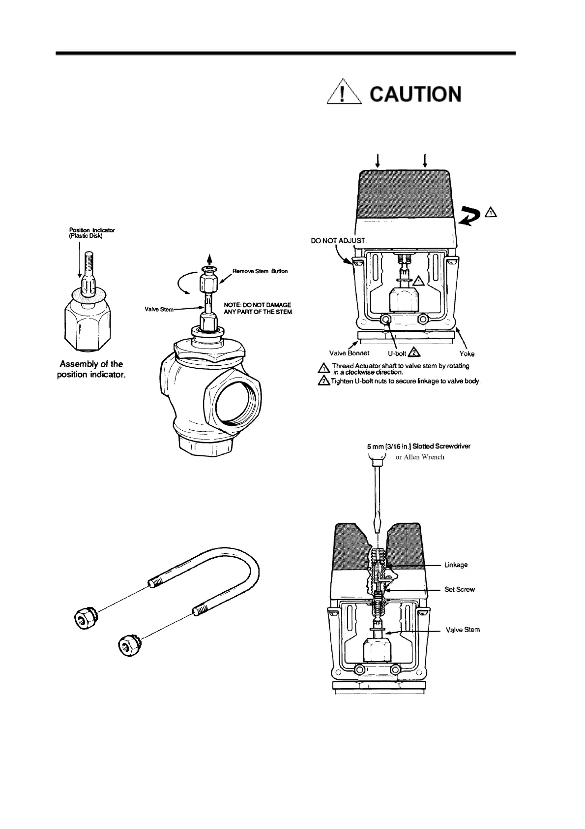
5. Remove the plastic cover from the ML6984 by loosening
the two screws located on the top (Note: These screws
are captive. Rotate three complete revolutions to remove
cover ). Drop either Slot Headed or Allen Hex type of set
screw (both are included in the plastic bag ) into the top of
the shaft, slotted/ Hexed side up. Or use the set screw
from the valve stem button.
6. Depending on which type of set screw was used, with a
5 mm (3/16") Slotted screwdriver or 1/8"x 6" Allen wrench
(included in the plastic bag), tighten the set screw to
lock valve stem in place (Fig. 6).
For proper valve operation, valve stem must be threaded
into the actuator all the way (with no threads showing)
and locked in place with the set screw provided.
FIG. 4 — ASSEMBLY OF ML6984A TO
FIG. 6. — LOCKING ML6984A DRIVE SHAFT TO
VALVE STEM
FIG. 3 — PREPARATION FOR VALVE ASSEMBLY
FIG. 5 — U-BOLT ASSEMBLY
 Loading...


