6
ML7984 Wiring
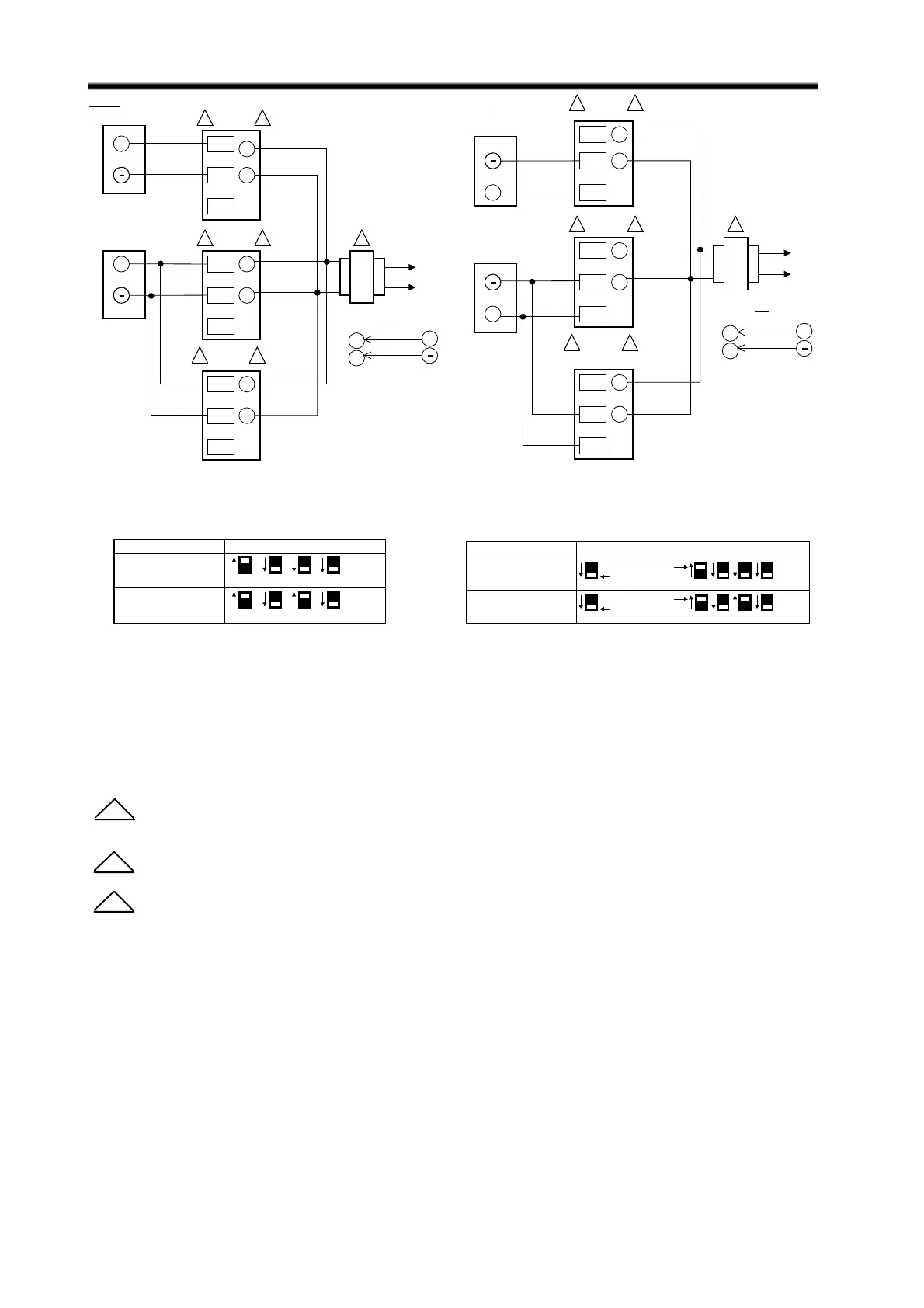
For Figures 8 and 9 the following apply:
Allow 0.5 amps maximum for each device. Actuators and controller can share same transformer providing
the VA rating of the transformer is not exceeded and proper phasing is observed.
“T5” and “W” terminals are factory connected internally. Device is compatible with the 3-wire control system.
Use configuration DIP switches to select device functions: Direct acting function ( actuator stem moves
upwards with signal increases ) or Reverse acting function ( actuator stem moves downwards with signal
increases ).
NOTE:
Always turn power off before setting the DIP switches.
FUNCTION DIP SWITCH CONFIGURATION
X000
4-20 mA Direct Acting
X010
20-4 mA Reverse Acting
On (1)
Off (0)
1
1
2
2
3
3
1
1
4
4
Master actuator
Master actuator
Slave actuator
Slave actuator
FUNCTION DIP SWITCH CONFIGURATION
1000
2-10 Vdc Direct Acting
1 2 3 4
1010
10-2 Vdc Reverse Acting
1 2 3 4
On (1)
Off (0)
On (1)
Off (0)
FIG. 8 — ML7984 WIRING WITH 10
VDC ANALOG CONTROL SIGNAL
FIG. 9 — ML7984 WIRING WITH 20mA
ANALOG CONTROL SIGNAL
1
2
3
3 ML7984
L1
L2
1
R
W
C
T6
T5
R
W
C
T6
T5
R
W
C
T6
T5
2
3 ML7984 2
3 ML7984 2
+
24 Vac
SIGNAL
SOURCE
OR
+
T6
T5
28 Vdc
+
3 ML7984
L1
L2
1
R
W
C
T6
T5
R
W
C
T6
T5
OR
R
W
C
T6
T5
2
3 ML7984 2
3
ML7984
(SLAVE)
2
SIGNAL
SOURCE
24 Vac
+
+
+
T6
T5
28 Vdc
 Loading...


