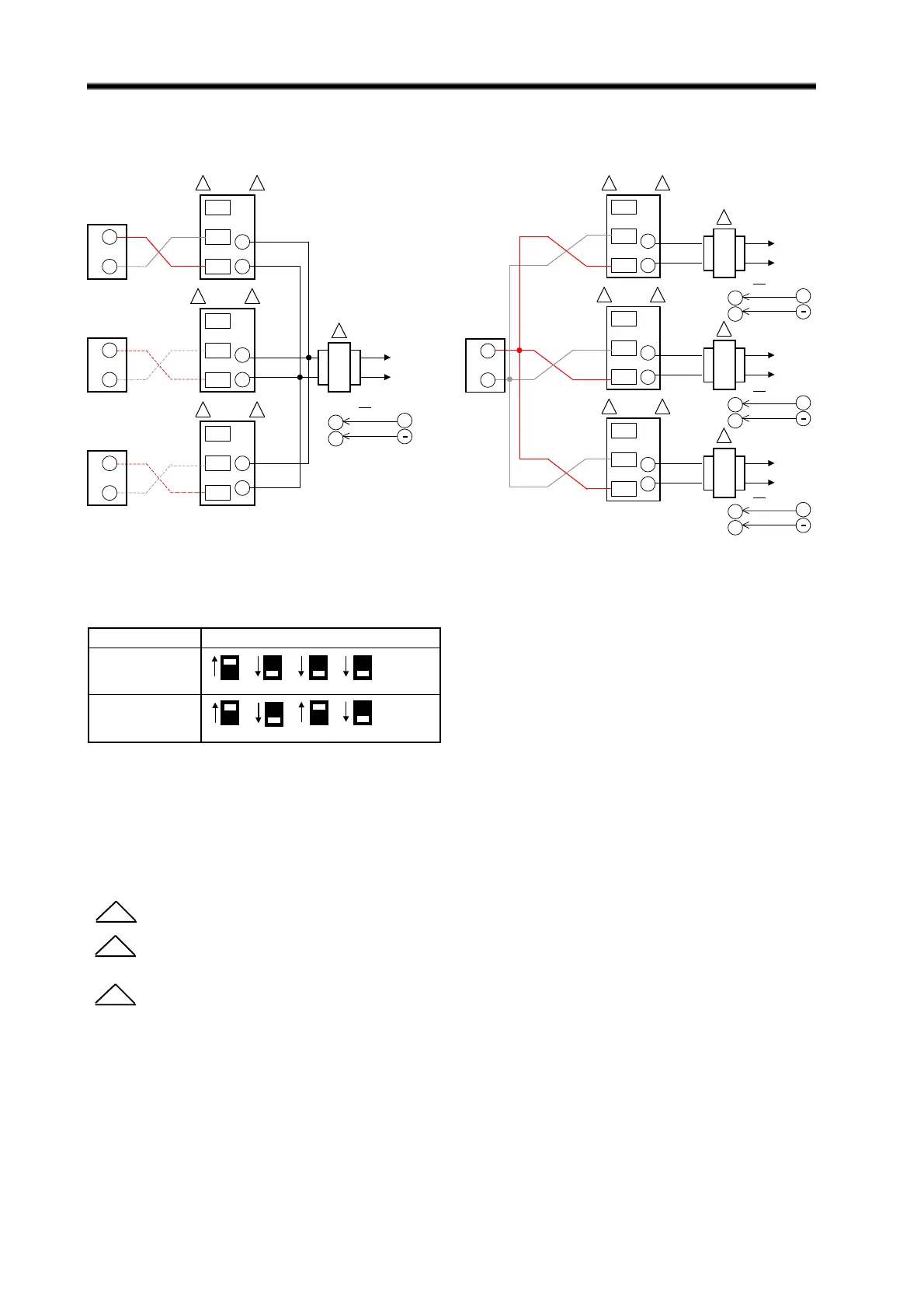
ML7984 Wiring
Allow 0.5 amps maximum for each device.
Do not mix M984/6 or Modutrol Motors with the ML7984 in the same circuitry.
Use configuration DIP switches to select device functions: Direct acting function ( actuator stem
moves upwards with signal increases ) or Reverse acting function ( actuator stem moves downwards with
signal increases ).
For Figure 11A and 11B only:
8
1
*Series 90 (mech/electronic) operation can
be reversed without changing wiring by
using DIP switch #3 (opposite as shown).
2
3
FIG. 11B — ML7984 WITH INDIVIDUAL
TRANSFORMERS, COMMON CONTROLLER
FIG. 11A — ML7984 WITH COMMON
TRANSFORMER, INDIVIDUAL CONTROLLERS
FIG. 11 — ML7984 WIRING WITH ELECTRONIC SERIES 90 “SUPERMOD” CONTROLLERS
3ML7984
L1
L2
1
B
R
W
T6
T5
B
R
W
T6
T5
OR
B
R
W
T6
T5
2
3ML79842
3ML79842
R
W
24 Vac
ELECTRONIC
SERIES 90
(W973, T775,
H775, W7100)
NOTE:
Polarity sensitive,
check connections W
to R, R to W
+
T6
T5
28 Vdc
R
W
R
W
3ML7984
L1
L2
1
B
R
W
T6
T5
B
R
W
T6
T5
OR
B
R
W
T6
T5
2
3ML79842
3ML79842
R
W
24 Vac
ELECTRONIC
SERIES 90
(W973, T775,
H775, W7100)
NOTE:
Polarity sensitive,
check connections
W to R, R to W
L1
L2
24 Vac
L1
L2
24 Vac
1
1
OR
OR
+
T6
T5
28 Vdc
+
T6
T5
28 Vdc
+
T6
T5
28 Vdc
FUNCTION DIP SWITCH CONFIGURATION
1000
Direct Acting
1010
Reverse Acting
On (1)
Off (0)
On (1)
Off (0)
3 4
21 3 4
21
 Loading...


