SERIES 61 AND SERIES 62 MODUTROL IV™ MOTORS
63-2629EF—01 8
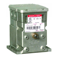
Fig. 6. Series 61 motor wiring.
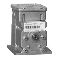
Fig. 7. Series 62 motor wiring.
Ensure that L1(hot) on the transformer matches 4
(internal hot) on the motor and L2 matches 3
(internal ground) on the motor.
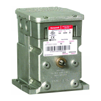
Fig. 8. Connections to R927C or R9107A Relay.
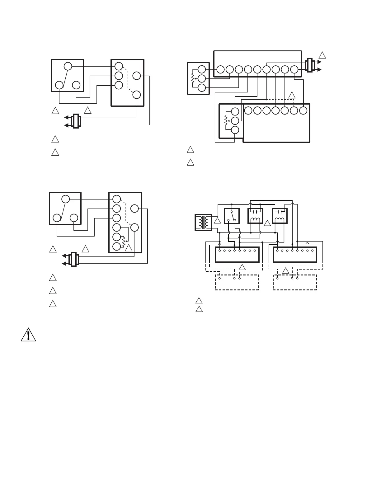
Fig. 9. Series 1 and Series 2 Parallel Application
R
B
W
R
W
B
T2
T1
(HOT) L1
L2
POWER SUPPLY. PROVIDE DISCONNECT MEANS
AND OVERLOAD PROTECTION AS REQUIRED.
TRANSFORMER MAY BE INTERNAL OR EXTERNAL
TO MOTOR.
M17095B
SERIES 60
CONTROLLER
SERIES 61
MOTOR
1
2
1
2
R
B
W
R
1
2
T
G
Y
4
3
(HOT) L1
L2
POWER SUPPLY. PROVIDE DISCONNECT MEANS
AND OVERLOAD PROTECTION AS REQUIRED.
TRANSFORMER MAY BE INTERNAL OR EXTERNAL
TO MOTOR.
FEEDBACK POTENTIOMETER.
M17096A
SERIES 60
CONTROLLER
SERIES 62
MOTOR
1
2
3
1
2
3
W
R
B
G
Y
T
POWER SUPPLY. PROVIDE DISCONNECT MEANS
AND OVERLOAD PROTECTION AS REQUIRED.
CONNECTION REQUIRED ONLY FOR SPRING RETURN MOTORS.
M17098A
SERIES 90
CONTROLLER
R927C OR R9107A RELAY
160 STROKE SERIES 62 MOTOR
Q181A
2
1
T
1
2
2
L1 (HOT)
L2
1
R
W
Y
T
G
2
B
R
W
B
1
4
3
M27044
TRANS
R
C
M62 S2
M62 S1
3
4
R1
T
2
G
Y
3
4
R1
T
2
G
Y
R
W
B
K1
K2
WIRING DIAGRAM M62XX SERIES 1 AND SERIES 2 PARALLEL APPLICATION
SIZE RELAYS AND TRANSFORMER PER SYSTEM REQUIREMENTS.
ADDITIONAL SERIES 2 OR SERIES 1 MOTORS CAN BE ADDED IN
PARALLEL. DO NOT MIX SERIES 1 AND SERIES 2 IN THE SAME
LINE. ONLY WIRE SERIES 1 WITH SERIES 1 AND SERIES 2 WITH
SERIES 2 IN PARALLEL.
1
2
2
2
1
1
M62 S2
M62 S1
3
1
2
3
1
2
 Loading...