SERIES 72 MODUTROL IV™ MOTORS
5 63-2202—4
INSTALLATION
When Installing this Product...
1.
Read these instructions carefully. Failure to follow them
could damage the product or cause a hazardous
condition.
2.
Check the ratings given in the instructions and on the
product to make sure the product is suitable for your
application.
3.
Installer must be a trained, experienced service
technician.
4.
After installation is complete, check out product
operation as provided in these instructions.
CAUTION
Electrical Shock or Equipment Damage Hazard.
Can shock individuals or short equipment
circuitry.
Disconnect all power supplies before installation.
Motors with auxiliary switches can have more than
one disconnect.
CAUTION
Equipment Damage Hazard.
Can damage the motor beyond repair.
Never turn the motor shaft by hand or with a wrench.
Forcibly turning the motor shaft damages the gear
train and stroke limit contacts.
IMPORTANT
Always conduct a thorough checkout when
installation is complete.
Location
Allow enough clearance for accessory installation and motor
servicing when selecting a location (see Fig. 1). If located
outdoors, use liquid-tight conduit connectors with the junction
box to provide NEMA 3 weather protection. If mounted
outdoors in a position other than upright, install a 4074ERU
Weatherproofing Kit and liquid-tight connectors to provide
NEMA 3 protection.
CAUTION
Motor Damage Hazard.
Deteriorating vapors and acid fumes can damage
metal parts.
Install motor in areas free of acid fumes and other
deteriorating vapors.
In excessive salt environments, mounting base and screws
should be zinc or cadmium plated, not stainless steel or brass.
Use the 220738A Adapter Bracket for mounting on these
surfaces.
Mounting
Use the following guidelines for proper motor mounting:
• Always install motors with the crankshaft horizontal.
• Mounting flanges extending from motor housing base are
drilled for 1/4 inch (6.4 mm) machine screws or bolts.
• Non-Spring Return Motors are shipped from the factory in
the closed position (at the counterclockwise rotation limit,
as viewed from the motor power end).
• Spring Return Motors are shipped from the factory in their
normal position.
• Normally closed models are shipped at the counterclockwise
rotation limit, as viewed from the motor power end.
• Normally open models are shipped at the clockwise
rotation limit, as viewed from the motor power end.
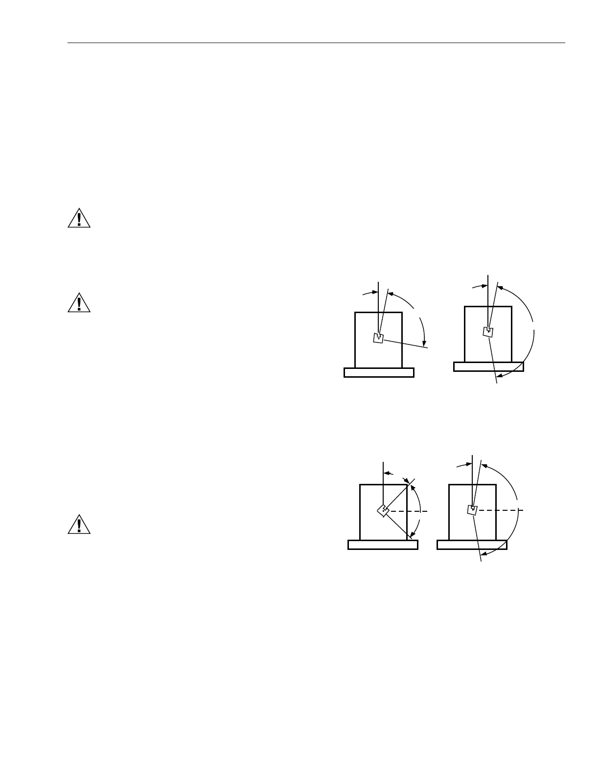
Fig. 2. Motor shaft position at limit of rotation
(viewed from motor power end).
FULLY OPEN
90 DEGREE STROKE
160 DEGREE STROKE
M5509
VERTICAL
REFERENCE
FULLY CLOSED
160
10
VERTICAL
REFERENCE
FULLY CLOSED
90
10
FULLY OPEN
VERTICAL
REFERENCE
VERTICAL
REFERENCE
FULLY CLOSED
FULLY OPEN
FULLY
CLOSED
FULLY
OPEN
90 DEGREE STROKE 160 DEGREE STROKE
NON-SPRING RETURN MOTORS
160
10
90
45
SPRING RETURN MOTORS
M7272, M7282, M7285, M7286
M7261, M7274, M7281, M7284, M7294
 Loading...