NO-400-006 2 I56-3524-006R
©2013 Notifier
FCC STATEMENT
This device complies with part 15 of the FCC Rules. Operation is subject to the following two conditions: (1) This device may not cause harmful interference, and (2) this device must accept any interference
received, including interference that may cause undesired operation.
NOTE: This equipment has been tested and found to comply with the limits for a Class B digital device, pursuant to Part 15 of the FCC Rules. These limits are designed to provide reasonable protection against
harmful interference in a residential installation. This equipment generates, uses and can radiate radio frequency energy and, if not installed and used in accordance with the instructions, may cause harmful
interference to radio communications. However, there is no guarantee that interference will not occur in a particular installation. If this equipment does cause harmful interference to radio or television reception,
which can be determined by turning the equipment off and on, the user is encouraged to try to correct the interference by one or more of the following measures:
– Reorient or relocate the receiving antenna.
– Increase the separation between the equipment and receiver.
– Connect the equipment into an outlet on a circuit different from that to which the receiver is connected.
– Consult the dealer or an experienced radio/TV technician for help.
Please refer to insert for the Limitations of Fire Alarm Systems
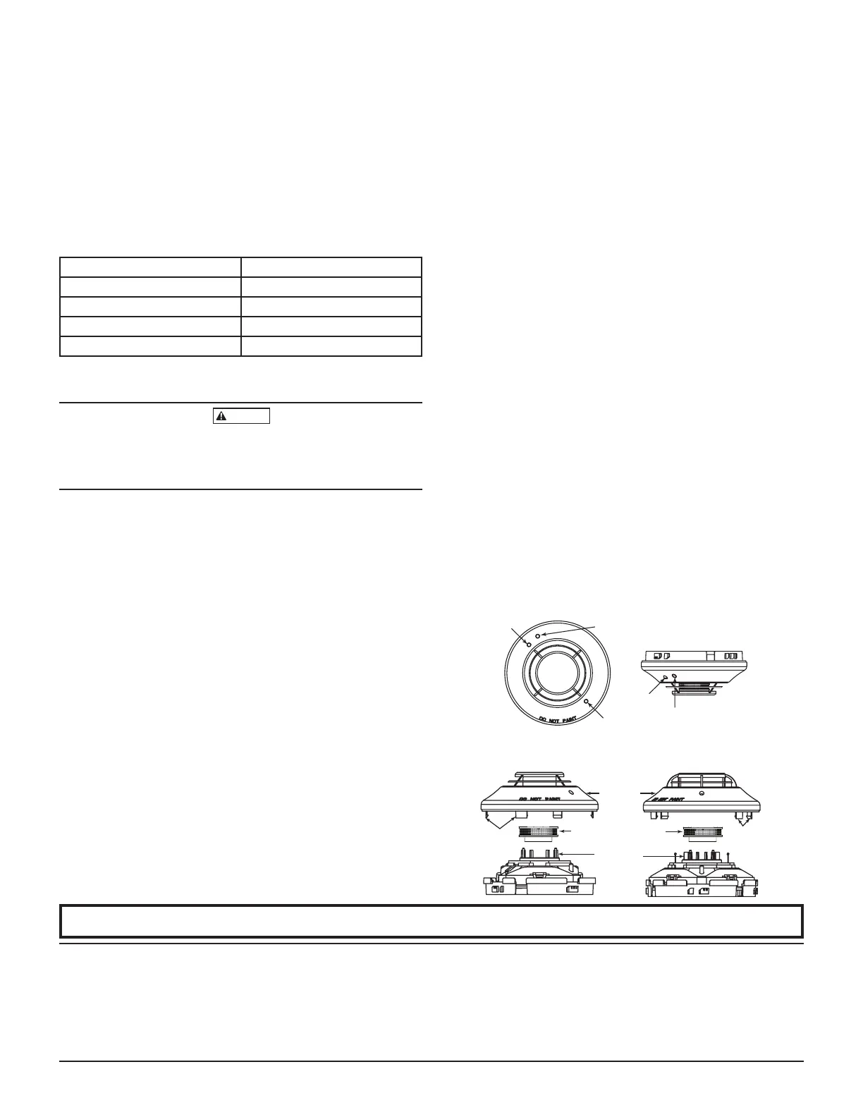
1. Hold the test magnet in the magnet test area as shown in Figure 3.
2. The sensor should alarm the panel.
Two LEDs on the sensor are controlled by the panel to indicate sensor
status. Coded signals, transmitted from the panel, can cause the LEDs
to blink, latch on, or latch off. Refer to the control panel technical docu-
mentation for sensor LED status operation and expected delay to alarm.
B. Smoke Entry
The GEMINI model 501 aerosol generator can be used for smoke entry
testing. Set the generator to represent 4%/ft to 5%/ft obscuration as de-
scribed in the GEMINI 501 manual. Using the bowl shaped applicator,
apply aerosol until the panel alarms.
Additionally, canned aerosol simulated smoke (canned smoke agent)
may be used for smoke entry testing of the smoke detector. Tested and
approved aerosol smoke products are:
Manufacturer Model
Home Safeguard Industries 25S
SDi CHEK02 and CHEK06
SDi SOLOA4
SDi SMOKESABRE-01
When used properly, the canned smoke agent will cause the smoke detector
to go into alarm. Refer to the manufacturer’s published instructions for proper
use of the canned smoke agent.
Canned aerosol simulated smoke (canned smoke agent) formulas will vary by
manufacturer. Misuse or overuse of these products may have long term ad-
verse effects on the smoke detector. Consult the canned smoke agent manufac-
turer’s published instructions for any further warnings or caution statements.
For FAPT-851, smoke entry testing should be performed immediately fol-
lowing the magnet test. Magnet test initiates an approximately 10 minute
period when the detector’s signal processing software routines are not
active. Failure to first perform the magnet test will introduce a time delay
before the detector alarms.
C. Direct Heat Method (Hair dryer of 1000-1500 watts). FSP-851T and
FAPT-851 only.
A hair dryer of 1000-1500 watts should be used to test the thermistors. Di-
rect the heat toward either of the two thermistors, holding the heat source
approximately 12 inches from the detector in order to avoid damaging
the plastic housing. The detector will reset only after it has had sufficient
time to cool. Make sure both thermistors are tested individually.
A sensor that fails any of these tests should be cleaned as described under
CLEANING, and retested. If the sensor fails after cleaning, it must be replaced
and returned for repair.
When testing is complete, restore the system to normal operation and notify
the proper authorities that the system is back in operation.
HIGH SENSITIVITY SETTING (Applies to FSP-851 and FSP-851T only)
The use of the 0.2% to 0.5% per foot sensitivity setting requires a 90-day test
period to ensure that the detector’s environment is suitable for this setting.
The following steps must be followed to meet Notifier and UL requirements
for this high sensitivity application:
1. Each detector intended for 0.2% to 0.5% per foot alarm application shall
have its initial alarm setting set for 0.5% obscuration per foot alarm level.
The initial pre alarm setting for the detector shall be set to the intended alarm
setting of the system. Pre alarm shall be set for non latching operation.
2. Detectors set at 0.2% to 0.5% per foot are intended for use in smoke-
free, environmentally controlled applications, such as computer rooms
and clean rooms. In order to determine if an environment is suitable for
installation, the detectors shall be operated continuously for 90 days with
all environmental factors, including temperature, humidity, air flow, oc-
cupancy, etc., similar to the intended application for these detectors. An
electronic history file or printer shall be used to record all events associ-
ated with the detectors under testing.
3. At the end of 90 days, the results of the test shall be inspected by an
authorized Notifier representative or the end user, if trained by an autho-
rized Notifier representative. If no alarms or pre alarms are recorded for
the detectors under testing, the system may be set to the tested pre alarm
level in the 0.2% to 0.5% per foot range.
CLEANING
Before removing the detector, notify the proper authorities that the smoke detec-
tor system is undergoing maintenance and will be temporarily out of service.
Disable the zone or system undergoing maintenance to prevent unwanted alarms.
1. Remove the sensor to be cleaned from the system.
2. Remove the sensor cover by pressing firmly on each of the four removal
tabs that hold the cover in place.
3. Vacuum the screen carefully without removing it. If further cleaning is
required continue with Step 4, otherwise skip to Step 7.
4. Remove the chamber cover/screen assembly by pulling it straight out.
5. Use a vacuum cleaner or compressed air to remove dust and debris from
the sensing chamber.
6. Reinstall the chamber cover/screen assembly by sliding the edge over the
sensing chamber. Turn until it is firmly in place.
7. Replace the cover using the LEDs to align the cover and then gently
pushing it until it locks into place. Make sure that the thermistors do not
become bent under the cover on the FSP-851T and FAPT-851 models.
8. Reinstall the detector.
9. Test the detector as described in TESTING.
10. Reconnect disabled circuits.
11. Notify the proper authorities that the system is back on line.
SPECIAL NOTE REGARDING SMOKE DETECTOR GUARDS
Smoke detectors are not to be used with detector guards unless the combina-
tion has been evaluated and found suitable for that purpose.
FIGURE 3:
LED
LED
MAGNET
TEST MARKER
LED
MAGNET
TEST MARKER
C0196-04
FIGURE 4:
COVER
REMOVAL
TABS
SENSOR
COVER
SENSING CHAMBER
COVER AND SCREEN
SENSING
CHAMBER
COVER
REMOVAL
TABS
FSP-851
FSP-851T AND FAPT-851
C1014-08

 Loading...