19 68-0173—3
3.
Remove the PC8900A from the wiring wallplate by
pulling the PC8900A straight off the wallplate.
4.
Position the PC8900A Wiring Plate on the wall.
5.
Level the wiring plate (for appearance only) using the
posts on top of the wiring plate; device functions
properly even when not level.
6.
Remove wiring plate from wall and drill 3/16 in. holes in
wall (if drywall) as marked. For firmer material such as
plaster or wood, drill 7/32 in. holes. Gently tap anchors
(provided) into drilled holes until flush with the wall.
NOTE: When using a wall cover plate, be sure to place
the wall cover plate between the wall and the
wiring plate.
7.
Position wiring plate over holes in wall or outlet box,
pulling wires through wiring opening. Loosely insert
three mounting screws into holes that best fit the
application.
8.
Tighten the mounting screws.
9.
Reinstall the PC8900A on the wallplate by pressing the
PC8900A directly onto the wallplate.
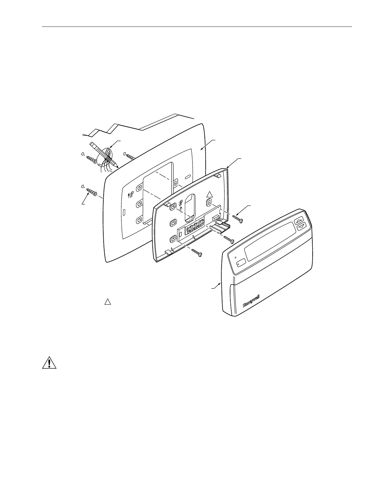
Fi
. 23. Mountin
PC8900A Wirin
Plate and 205224A Wall Cover Plate to wall.
Wiring the PC8900A
CAUTION
Keep wirin
at least one foot awa
from lar
e
inductive loads such as motors, line starters,
li
htnin
ballasts and lar
e power distribution
panels. Failure to follow these wirin
practices can
introduce electrical interference (noise), which can
cause erratic s
stem operation. Use shielded
cable to reduce interference if reroutin
of wirin
is not possible. Ground the shielded cable onl
to
GND terminal on W8900A-C.
IMPORTANT
Erratic temperature readings can occur as a result of
any of the wiring practices described below. These
practices must be avoided to assure proper
operation. Use shielded cable to reduce interference
if rerouting of wiring is not possible.
— Do not route thermostat wiring with building power
wiring, next to control contactors or near light
dimming circuits, electric motors or welding
equipment.
— Avoid poor wiring connections.
— Avoid intermittent or missing building earth ground.
CHECK
SYSTEM
WIRES THROUGH
WALL OPENING
205224A
WALL COVER PLATE
PC8900 WIRING
PLATE
MOUNTING
SCREWS (3)
PC8900
COMFORT
CENTER
CONTROL
PANEL
M7512A
CHOOSE THREE MOUNTING HOLES
THAT BEST FIT APPLICATION.
1
1
WALL
ANCHORS
(3)