Q7055C BUILDING NETWORK ADAPTERS BNA-1C/2CS
3 95-7735
Fig. 3. Stacked Devices.
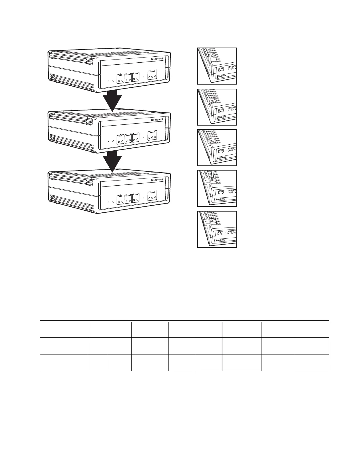
Wall Mounting
It is also possible to mount the BNA device to a wall. The
following sequence describes how the device should be
prepared prior to mounting it on a wall (see Fig 4). Fig. 4. BNA wall mount.
Communications Panel Mounting
It is also possible to mount the BNA device in the 14006090-
555151 series Communications Panel (see Fig. 5). This
method of mounting is recommended for smoke control
applications.
Table 1. C-Bus Connector Terminal Specifications.
* supervised spaces Max wiring distance 4,000 ft. (1,219m), 18AWG min.
BUILDING NETWORK ADAPTER M
ODEL
2CS
Reset Power
LAN
10
ACT
Mode
Ch2
Rx
Tx
Ch1
Rx
Tx
100
Boot
NML
BUILDING NETWORK ADAPTER M
ODEL
2CS
Reset Power
LAN
10
ACT
Mode
Ch2
Rx
Tx
Ch1
Rx
Tx
100
Boot
NML
BUILDING NETWORK ADAPTER M
ODEL
2CS
Reset Power
LAN
10
ACT
Mode
Ch2
Rx
Tx
Ch1
Rx
Tx
100
Boot
NML
M25115
Place the BNA-adapter with the topside
down on the desk.
Remove the four feet from the bottom of
the BNA by pushing horizontally away from
the housing with a flat screwdrive r .
Push the four inserts (included) fully and
horizontally into the housing.
Adjust the four retaining clips (included) on
top of the inserts. Fasten the retaining clips
with the included four screws.
Use the housing with the clips to mark the
positions of the four mounting holes on the
wall surface. Drill 1/8 in. (3 mm) holes for
the mounting screws (not included) and fix
the BNA device.
M22
A
Ch2
LAN
10
ACT
Rx
Tx
Mode
Ch1
Rx
Tx
100
Ch2
LAN
10
ACT
Rx
Tx
Mode
Ch1
Rx
Tx
100
Ch2
LAN
10
ACT
Rx
Tx
Mode
Ch1
Rx
Tx
100
Ch2
LAN
10
ACT
Rx
Tx
Mode
Ch1
Rx
Tx
100
Ch2
LAN
10
ACT
Rx
Tx
Mode
Ch1
Rx
Tx
100
Connector
Terminal Pin
Signal
Type
Input/
Output
Voltage
Type
Max.
Voltage Max. Current
Max.
Frequency
Max.Line
Impedance
CH1/CH2 RS-485
(C-BUS)*
A(+) +In Input/Output SIGNAL ±5 V 1 mA/ 180 mA 9600 baud 100 ohms
CH1/CH2 RS-485
(C-BUS)*
B(-) -In Input/Output SIGNAL ±5 V 1 mA/ 180 mA 9600 baud 100 ohms
 Loading...