Q7055C BUILDING NETWORK ADAPTERS BNA-1C/2CS
5 95-7735
CONNECTIONS
This section describes how to connect power and the field bus
to the BNA device. A supply pack with installation material
containing the required connectors for power and the field bus
are shipped with the device.
Power Connection
The BNA device requires a UL 864 listed external power
supply with the following specifications: 24 VAC, 50 to 60 Hz,
or 24 VDC.
Typical power supplies include:
DC Power Supply: 50017367-001 Jameco
®
Model No.
DDU240050, 120 VAC, 60 Hz 15 VA input, 24 VDC, 0.500
Amp output, wall mounted power cube Class 2 (included).
AC Power Supply: 120 VAC/50 to 60 Hz input, 24 VAC output,
14507287 series.
Power consumption of the BNA device is 8 VA.
For the power connection, the 3-pole Phoenix connector is
required (included).
Wire the power cable as follows:
1. Cut off the original connector at the end of the cable. In
case of a DIN connector equipped power cable, identify
the 24 VDC cable pair using a multimeter. If the power
supply has screw terminals, wire a cable to the 24 V and
GND terminals on the power supply.
2. Strip the two power cable ends and insert each cable
end into the openings of the 3-pole Phoenix connectors
that are marked for power.
3. Fasten them with a screwdriver.
4. Connect a chassis ground to the third position on
this connector as marked.
NOTE: The polarity (+/-) of the 3-pole Phoenix power con-
nector for DC power supplies is don't care.
Field Bus Connection (Ch1/Ch2)
For connecting the field bus, the 2-pole or 3-pole Phoenix
connectors (included) are required. Field bus connection can
be configured only as class B/style 4. All field wiring is
supervised.
Consult form no. 74-4047, Q7055C Building Network Adapter
BNA-1C/2CS Checkout & Test for additional information on
field bus wiring.
CABLES AND CONNECTORS
DB9F Null Modem Connector
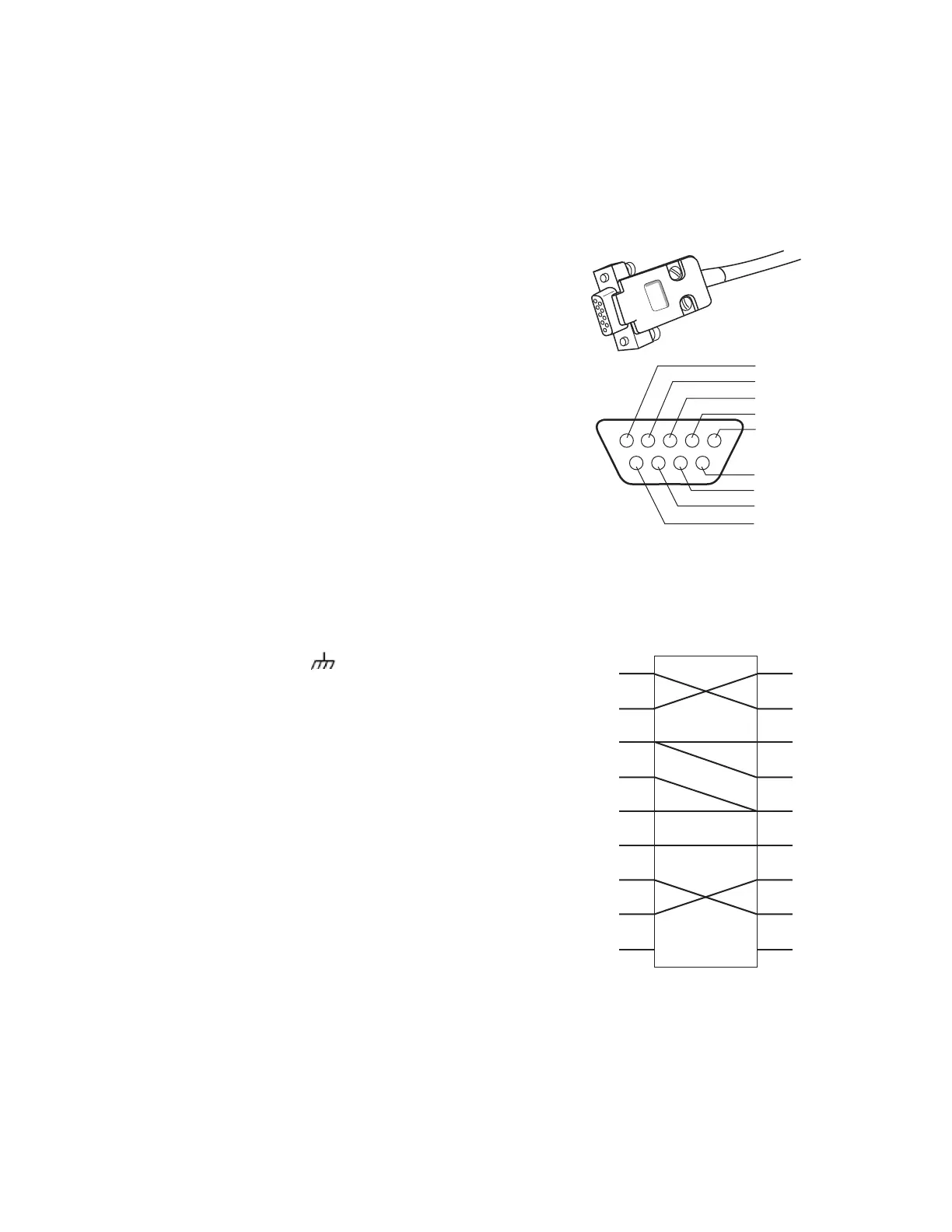
Fig. 6 illustrates a serial connector for the field bus. Fig. 7
shows how to configure a Null Modem Cable DB9F.
Fig. 6. Serial connector (female connector is numbered as
shown).
Fig. 7. Signal connections for DB9F Null Modem Cable.
9 = RI
5 = GROUND
8 = CTS
7 = RTS
6 = DSR
M19592
2 = RxD
3 = TxD
4 = DTR
1 = DCD
DCD
DSR
GND
RTS
CTS
DTR
RxD
2
3
4
1
6
5
7
8
2
3
6
1
4
5
7
8
TxD
RI
DCD
DTR
GND
RTS
CTS
DSR
RxD
TxD
RI
M19594
99
 Loading...