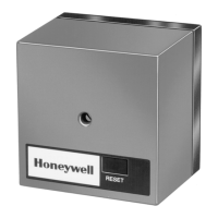
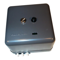
R7284B,P,U,G ELECTRONIC OIL PRIMARY, ENVIRACOM™ ENABLED
69-2467EFS—09 8
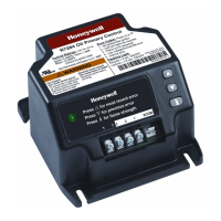
BASIC USER INTERFACE
The basic user interface consists of 3 buttons and an
LED. Simple diagnostic information can be obtained
through the interaction of the buttons and LED.
R7284 Status (Basic Interface)
Table 2. LED Codes.
R7284 Flame Strength
(Basic Interface)
During normal operation and when the R7284 is in the
Running state, the LED will show CAD cell resistance.
See Table 3.
Table 3. Flame Strength Indication.
Error History (Basic Interface)
The last two errors are available for display on the
LED:
• Pressing the up arrow button displays the most
recent error.
• Pressing the down arrow button displays the next
most recent error.
Once the up or down arrow is pushed, the LED will
display the most recent or next most recent alarm by
blinking the error code. See Table 4.
R7284 Error Codes
(Basic Interface)
Table 4. Error Codes.
TROUBLESHOOTING AND
MAINTENANCE
IMPORTANT
Due to the potential hazard of line voltage,
only a trained, experienced service technician
should preform the troubleshooting
procedures.
This control contains no field-serviceable
parts. Do not attempt to take it apart. Replace
entire control if operation is not as described.
To completely troubleshoot an oil burner installation,
check the burner and oil primary control for proper
operation and condition.
Cad Cell Resistance Check
For proper operation, it is important that the cad cell
resistance is below 1600 ohms. On the basic model
with LED interface, during a normal call for heat, once
the control has entered the Run mode, press and
release the “i” button.
On the advanced model with display, follow the screen
diagnostic procedure to read the cad cell resistance.
Cad cell resistance can be checked without using an
ohm meter.
Preliminary Steps
1. Check wiring connections and power supply.
2. Make sure power is on to controls.
3. Make sure limit control is closed.
4. Check contacts between igniter and the elec-
trodes.
5. Check the oil pump pressure.
6. Check the piping to the oil tank.
7. Check the oil nozzle, oil supply and oil filter.
Check Oil Primary Control
If the trouble is not in the burner or ignition hardware,
check the oil primary control by using the following
equipment:
1. Screwdriver.
2. Voltmeter (0 to 150 Vac range).
3. Insulated jumper wire with both ends stripped.
Description LED Code
Standby Pulse (1/4 sec. ON, 4 sec OFF)
Call for Heat
Heartbeat (1/2 sec bright, 1/2 sec dim)
Flame proven On solid
Recycle 2 second ON, 2 second OFF flashing
Lockout 1/2 second on, 1/2 second OFF
flashing
Interrupt OFF
“i” button Flame Strength Indication
Up button Most recent error
Down button Next most recent error
Flame Strength
Indication
Number of 1/2 sec
flashes
Cad Cell less than 400Ω 1
400Ω < Cad Cell < 800Ω 2
800Ω < Cad Cell < 1600Ω 3
1600Ω < Cad Cell < 6100Ω 4
Cad Cell > 6100Ω None
Error Codes
Number of 1/4
sec flashes
No ignition / Late ignition 1
Max flame losses / Cad Cell high
while running
2
Flame out of sequence 3
Low Voltage / EnviraCOM™ error 4
Internal Error 5
 Loading...