EasyManua.ls Logo

Honeywell RM7897C1000 - User Manual

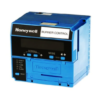
Honeywell RM7897C1000
16 pages
Print Icon
To Next Page IconTo Next Page
Loading...
INSTALLATION INSTRUCTIONS
66-1151
RM7897A1002, RM7897C1000
7800 SERIES
Relay Modules
APPLICATION
The RM7897A,C are microprocessor-based integrated burner
controls for automatically fired gas, oil, or combination fuel
single burner applications. The RM7897A,C system consist of
a relay module, subbase, amplifier, and purge card. Options
include keyboard display module (KDM), Personal Computer
Interface, Data ControlBus™ Module, remote display
mounting, Expanded Annunciator and Combustion System
Manager® Software.
Functions provided by the RM7897A,C include automatic
burner sequencing, flame supervision, system status
indication, system or self-diagnostics and troubleshooting.
The RM7897 adds a proof of closure input to the standard
primary control function of the RM7895/RM7896 product. It
adds a blinking fault code function to the POWER LED on
Alarm shutdown. It also adds programmable postpurge using
the S7800A1142 Keyboard Display Module (KDM). The
RM7897A1002 offers selectable pilot operation, intermittent
on terminal 8 or interrupted on terminal 21.
The RM7897C1000 offers interrupted pilot and delayed main
valve for 2-step firing (Low-High-Low) applications.
This document provides installation and static checkout
instructions. Other applicable publications are:
SPECIFICATIONS
Electrical Ratings (See Table 3):
Voltage and Frequency:
RM7897A,C: 120 Vac (+10/-15%), 50/60 Hz (± 10%).
Power Dissipation: 10W maximum.
Maximum Total Connected Load: 2000 VA.
Fusing Total Connected Load: 15A Fast Blow, type SC or
equivalent.
Environmental Ratings:
Ambient Temperature:
Operating: -40°F to 140°F (-40°C to +60°C).
Storage: -40°F to 150°F (-40°C to +66°C).
Humidity: 85% relative humidity continuous, noncondensing.
Vibration: 0.5G environment.
Approvals:
Underwriters Laboratories Inc. Listed: File No. MP268,
Guide No. MCCZ.
Canadian Standards Association Certified: Pending.
Factory Mutual Approved: Report No. Pending.
IRI Acceptable.
Federal Communications Commission: Part 15, Class B,
Emissions.
Publication
No. Product
63-2278 Q7700 Network Interface Unit Product Data
65-0084 Q7800A,B 22-Terminal Wiring Subbase
Product Data
65-0288 S7800A1142 Keyboard Display Module
Product Data
65-0091 S7810A Data ControlBus Module™ Product
Data
65-0095 S7820 Remote Reset Module Product Data
65-0097 221729C Dust Cover Installation
Instructions
65-0101 S7830 Expanded Annunciator Product Data
65-0102 ZM7850A Combustion System Manager™
Operating Instructions
65-0109 R7824, R7847, R7848, R7849, R7851,
R7861, R7886 Flame Amplifiers for the
7800 Series Product Data
65-0131 221818A Extension Cable Assembly
Product Data
65-0229 7800 SERIES Relay Modules Checkout and
Troubleshooting Product Data.
65-0092 QS7800A ControlBus™ Module, Standard
65-0227 QS7800B ControlBus™ Module, Multidrop
Publication
No. Product


Questions and Answers

  • N
    Nicholas PatelSep 3, 2025
    What causes wiring problem or internal fault in Honeywell RM7897C1000 Control Unit?
    • C
      Chelsea FrySep 3, 2025
      If the Honeywell Control Unit reports a 'Wiring Problem/ Internal Fault', indicating that a pilot (ignition) valve terminal, main valve, ignition, or Main Valve 2 was on when it should be off, take the following precautions: remove system power and turn off the power supply and fuel supply. Check the wiring and correct any errors. Inspect the Pilot Fuel Valve(s) and connections. Reset and sequence the relay module. If the fault persists, replace the relay module.
  • L
    Lee GainesSep 18, 2025
    How to troubleshoot device specific fault on Honeywell RM7897C1000?
    • S
      Steve ValdezSep 18, 2025
      If your Honeywell Control Unit displays a 'Device Specific' fault related to special OEM input circuits, check the wiring and operation of these special OEM inputs. Reset and sequence the relay module. If the fault reappears, remove power from the device, reapply power, and then reset and sequence the relay module. If the fault does not repeat on the next cycle, check for electrical noise being copied into the relay module through the external loads or possibly an electrical grounding issue. If the fault persists, replace the relay module.
  • R
    Robert HancockSep 16, 2025
    What causes internal faults in Honeywell RM7897C1000?
    • D
      Douglas WalkerSep 16, 2025
      If your Honeywell Control Unit is displaying 'Internal Faults' due to a Relay Module Self-Test failure, reset and sequence the relay module. If the fault reappears, remove power, reapply power, and then reset and sequence the relay module. If the fault does not repeat on the next cycle, check for electrical noise being copied into the relay module through the external loads or possibly an electrical grounding issue. If the fault persists, replace the relay module.
  • M
    Matthew MorganSep 14, 2025
    How to fix internal faults on Honeywell RM7897C1000 Control Unit?
    • T
      Terry PowersSep 14, 2025
      If your Honeywell Control Unit is displaying 'Internal Faults' indicating a Relay Module self-test failure, reset and sequence the relay module. If the fault reappears, remove power from the device, reapply power, and then reset and sequence the relay module. If the fault persists, replace the relay module.
  • R
    richvalerieSep 12, 2025
    Why is man-open switch, start switch, or control on in wrong state on Honeywell RM7897C1000 Control Unit?
    • J
      John PetersonSep 12, 2025
      If your Honeywell Control Unit shows a problem with the 'Man-Open Switch; Start Switch or Control On' being in the wrong operational state, check the wiring and correct any errors. Make sure that the Manual Open Valve Switch, Start Switch, and Control are operating properly. Note if the Stat Switch is held “On” too long. Reset and sequence the relay module. If the fault persists, replace the relay module (RM7838A1014; RM7838B1013 or RM7838C1004 only).
  • D
    Daniel FrancisSep 12, 2025
    What causes high fire switch or low fire switch failure on Honeywell Control Unit?
    • M
      Mary BrownSep 12, 2025
      If your Honeywell Control Unit indicates a 'High Fire Switch or Low Fire Switch' failure, check the wiring and correct any errors. Reset and sequence the relay module. Use the manual motor potentiometer to drive the motor open and closed, verifying at the motor switch that the end switches are operating properly. If a manual potentiometer is unavailable, use the RUN/TEST switch. Reset and sequence the relay module. If the fault persists, replace the relay module.
  • F
    frobertsonSep 9, 2025
    How to troubleshoot preignition interlock on Honeywell RM7897C1000?
    • E
      Ebony ShepardSep 9, 2025
      If your Honeywell Control Unit is experiencing a 'Preignition Interlock' fault, check the wiring and correct any errors. Check the Preignition Interlock switches to ensure they are functioning properly. Also, check the fuel valve operation. Reset and sequence the relay module while monitoring the Preignition Interlock status. If the fault persists, replace the relay module.
  • J
    Jennifer EstradaSep 7, 2025
    What to do if Honeywell Control Unit shows configuration jumper problem?
    • E
      Eric JordanSep 7, 2025
      If the Honeywell Control Unit displays a 'Configuration Jumper Problem', indicating that the configuration jumpers differ from the sample taken at startup, inspect the jumper connections, ensuring that any clipped jumpers were completely removed. Reset and sequence the relay module. If the fault persists, replace the relay module.
  • L
    Laura BradySep 5, 2025
    How to fix flame amplifier problem on Honeywell RM7897C1000 Control Unit?
    • J
      jennifercameronSep 5, 2025
      If the Honeywell Control Unit displays a 'Flame Amplifier Problem', where flame is not sensed, or sensed when it should be on or off, check the wiring and correct any errors. Ensure the flame amplifier and flame detector are compatible. Remove the flame amplifier and inspect the connections, then reseat the amplifier. Reset and sequence the relay module. If the code reappears, replace the flame amplifier and/or the flame detector. If the fault persists, replace the relay module.
  • T
    Timothy GutierrezAug 20, 2025
    How to fix low AC line voltage on Honeywell RM7897C1000 Control Unit?
    • T
      Theresa CastanedaAug 20, 2025
      If your Honeywell Control Unit displays 'Low AC Line Voltage', start by checking the connections of the relay module and display module. Then, try resetting and sequencing the Relay Module. Also, check the 7800 power supply to ensure the frequency and voltage meet the required specifications. Finally, inspect the backup power supply if applicable.

Summary

INSTALLATION INSTRUCTIONS

Installation Precautions and Warnings

Covers critical safety warnings and general precautions before installation.

WIRING GUIDELINES AND DIAGRAMS

Wiring Warnings and Block Diagram

Highlights electrical shock hazards, internal block diagram, and recommended wire routing.

WIRE, GROUNDING, AND FINAL WIRING CHECKS

STATIC CHECKOUT PROCEDURES

TESTING GUIDELINES AND MODULE MOUNTING

STATIC CHECKOUT TABLE AND KDM SETUP

Static Checkout Steps

Presents the step-by-step table for performing static checkout tests.

PRINCIPAL TECHNICAL FEATURES AND OPERATION

RUN;TEST SWITCH AND CONFIGURATION

TROUBLESHOOTING AND FAULT CODES

Jumpers and Fault Identification

Shows jumper locations and introduces troubleshooting using blinking LED fault codes.

Blinking Fault Codes Table

Lists initial fault codes, system failures, and recommended troubleshooting steps.

CONTINUED TROUBLESHOOTING AND FAULT CODES

CONTINUED TROUBLESHOOTING AND COMPANY INFORMATION

Honeywell RM7897C1000 Specifications

General IconGeneral
TypeControl Unit
SeriesRM7897
Input Voltage24 VAC
Voltage24 VAC
Output Voltage24V AC/DC
Frequency50 Hz; 60 Hz
Humidity Range0 to 95% RH
ApprovalsCE, UL
ApplicationIndustrial

Related product manuals