INSTALLATION INSTRUCTIONS
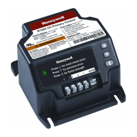
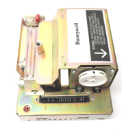
R7284B,P,U,G
Electronic Oil Primary,
EnviraCOM™ Enabled
APPLICATION
The R7284B,P,U,G Electronic Oil Primary is a line
voltage, safety rated, interrupted and intermittent
ignition oil primary control for residential oil fired
burners used in boilers, forced air furnaces and water
heaters. The R7284B,P,U,G used with a cad cell flame
sensor operates an oil burner, spark igniter, and
optional oil valve. The control works with a low voltage
and optional high voltage thermostat. The primary
controls fuel oil, senses flame, controls ignition spark
(either interrupted or intermittent) and notifies
through the EnviraCOM™ bus a remote alarm circuit
when in lockout.
The R7284 Series of Oil Primary Controls can be used
with both hydronic and forced air systems. When
used with hydronic systems, line voltage switching
Aquastat® Controllers normally provide for the
starting and stopping of the combustion sequences.
With forced air systems, both mechanical and
electronic low voltage thermostats control the
starting and stopping of the combustion process.
Some hydronic and forced air systems require a
delayed valve-on and burner motor-off delay. The
R7284 operates an oil valve that prevents the flow of
oil when the burner motor is running prior to
combustion (delayed valve-on) and when the burner
motor is running after combustion (burner motor-off
delay).
The R7284 models are intended for use only on oil
burning appliances which do not require prepurge
and post-purge as a safety related function as
defined in UL296. The valve-on delay and burner
motor-off delay in this control are intended only to
help establish draft and reduce oil after-drip related
problems.
EnviraCOM™ enabled R7284’s can be used with
EnviraLink® remote monitoring systems and hand-
held diagnostics. Use only R7284P and U models for
networking with other EnviraCOM™ enabled devices.
FEATURES
User Interface
There are two user interfaces: basic and advanced.
Both interfaces consist of three buttons: , , and “i.”
The advanced interface has a two-line display used to
configure device parameters, retrieve diagnostic
information, and display system status.
The basic interface has a single LED used to display
error codes and system status.
In general, the “i” button cycles through the display
options and acts as an “enter” key (in setup modes).
Thermostat(s)
The oil primaries are compatible with both standard
thermostats and EnviraCOM™ communicating
thermostats.
Limited Recycle
This feature limits the number of recycle trials (for
each call for heat) to a maximum of three trials. If the
flame is lost three times and does not successfully
satisfy a call for heat, the R7284 locks out.
Pump Priming Cycle
To facilitate purging air from the oil lines and filters,
the R7284 can be placed in a purge routine by
pressing and releasing the up arrow button during
the Trial For Ignition.
In the advanced interface “PUMP PRIME” is
displayed on the display along with the time left on
the Trial for Ignition (TFI). Pressing the up arrow
button adds a minute to the TFI time for a maximum
of 10 additional minutes (press the up arrow button
10 times). Pressing the down arrow button subtracts
a minute from the TFI time.
There is no visual indication for the basic interface
control and the purge timing is limited to five
minutes.
Disable Function
Pressing and holding the “i” button will disable all
control functions until 3 seconds after the button is
released.
Lockout Modes
The R7284 has three types of lockout modes that are
entered when an error is encountered: