EasyManua.ls Logo

Honeywell R4795A

Honeywell R4795A
16 pages
To Next Page IconTo Next Page
Loading...
1 60-2285—7
R4795A
Flame Safeguard
Primary Controls
The R4795A Protectorelay™ Primary Control
provides solid state electronic flame safeguard
protection for commercial and industrial gas or oil
burners. It provides a prepurge period before each
start, and intermittent pilot.
120V models meet the requirements of Underwrit-
ers Laboratories Inc. Standard 795 for mechanical
draft and atmospheric burner inputs from 400,000 to
2,500,000 Btu.
Meets Underwriters Laboratories Inc. requirements
for oil burner group 8 when 30, 60, or 90 second pre-
purge timer is used.
Selection of solid state, plug-in prepurge timers pro-
vides 7, 10, 30, 60, or 90 second prepurge time.
Includes terminals for connection of air flow switch
to prove airflow before prepurge period starts, dur-
ing purge, and during the entire Run period.
Choice of interchangeable, color-coded, solid state,
plug-in flame signal amplifiers allows use with rec-
tification or ultraviolet type flame detectors.
Safe-start feature prevents start when flame or flame
simulating condition is present.
Recycles through prepurge if the flame goes out
while burner is running. If pilot flame is not re-
established, safety switch trips and locks out system.
A tripped safety switch must be manually reset to
restore operation.
Push-to-reset safety switch is dust-resistant enclosed.
Optional spdt alarm contacts operate external alarm
on safety switch lockout.
Ignition interference circuit (rectification amplifier
only) protects electronic network from high voltage
ignition crossover and provides visual indication
when interference occurs.
Solid state circuitry eliminates vacuum tube replace-
ment and increases resistance to vibration. Applica-
tion of power not required during Off cycle; no tube
warmup before starting.
Easy-to-replace plug-in components result in faster
service and reduced inventory.
Flame current jack, located on the amplifier, provides
means of plugging in a microammeter to measure the
flame signal with system operating.
Easy mounting and removal through use of captive
mounting screws, which also serve as electrical
connections.
Durable thermoplastic mounting base.
Models available with -40°F (-40°C) temperature
rating.
S.Y. • Rev. 12-94 • ©Honeywell Inc. 1994
60-2285-7
CONTENTS
Specifications ................................................. 2
Ordering Information ..................................... 2
Installation ..................................................... 4
Checkout......................................................... 8
Operation ..................................................... 11
Troubleshooting ........................................... 11
Service .......................................................... 13
Question and Answer IconNeed help?

Do you have a question about the Honeywell R4795A and is the answer not in the manual?

Honeywell R4795A Specifications

General IconGeneral
BrandHoneywell
ModelR4795A
CategoryControl Unit
LanguageEnglish

Summary

Specifications

Ordering Information

Installation

LOCATION AND ENVIRONMENTAL CONSIDERATIONS

Details ambient temperature, humidity, vibration, and weather requirements for proper installation.

MOUNTING AND WIRING SUBBASE

Instructions for mounting the subbase and connecting electrical wiring to the R4795.

SYSTEM WIRING AND RETROFITTING

Covers typical wiring hookups, retrofitting guidance, and specific wiring details.

SPECIFIC REPLACEMENT AND WIRING

Details on replacing older models, flame detector wiring, and alarm contact connections.

FINAL UNIT MOUNTING

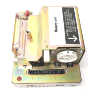
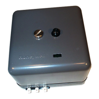
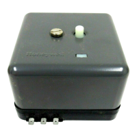
Instructions for securely mounting the R4795 unit onto the Q270 subbase.

Checkout

PRELIMINARY INSPECTION

Details initial checks to perform before system startup, including wiring and component seating.

FLAME CURRENT CHECK

Explains how to test flame detector application and identify potential signal issues.

PILOT TURNDOWN TEST

Provides procedure to ensure the pilot flame can safely light the main burner.

SAFE SHUTDOWN CHECKS

Describes tests for proper system response to limit action, flame failure, and power failure.

Operation

NORMAL OPERATION

Describes the sequence of events during a normal call for heat and burner operation.

SAFETY OPERATION

Details system responses to safety conditions like flame failure, airflow failure, and timer issues.

Troubleshooting

PRELIMINARY INSPECTION

Checks for proper seating of components and tight mounting screws before troubleshooting.

TROUBLE LIST

Lists common problems and their corresponding troubleshooting steps.

Service

GENERAL

Provides general guidelines for servicing heating equipment and controls safely and effectively.

PERIODIC MAINTENANCE

Outlines recommended maintenance tasks and their frequency for optimal system performance.

CONTACT CLEANING

Instructions and precautions for cleaning relay contacts using approved cleaners.

Related product manuals