EasyManua.ls Logo

Honeywell R4140G User Manual

Honeywell R4140G
32 pages
To Next Page IconTo Next Page
Page #1 background imageLoading...
Page #1 background image
INSTALLATION INSTRUCTIONS
Copyright © 1996 Honeywell Inc. • All Rights Reserved
R4140G,L and M
Flame Safeguard Programming Controls
60-0770-2
IMPORTANT
Applications, Features, Specifications (including
dimension drawings), Operation (including
schematics and bar charts), and Wiring Diagrams
are included in these Specifications for models of
the R4140G, L, and M: R4140G—60-2337;
R4140L—60-2339; R4140M—60-2340.
Contents
Installation ........................................................................... 2
Checkout ............................................................................. 11
Troubleshooting .................................................................. 18
Service Information ............................................................. 27
Testing and Maintenance .................................................... 28
Fig. 2. Components of R4140L Programmers.
RESET BUTTON
RELAY/TIMER
COVER
FLAME SIGNAL
METER JACK
TIMER DIAL
TIMER
RELAY
2K
RELAY
3K
RELAY 1K
RELAY 4K
TIMER
MOTOR
HINGE
BRACKET (2)
CHASSIS
SAFETY SWITCH
BUTTON
CHASSIS RETAINING
SCREW
HANDLE
TIP JACK
PLUG-IN
FLAME SIGNAL
AMPLIFIER
M7959
OPTIONAL HEAVY DUTY
COVER (PART NO.
202050C OR 139695C)
RESET BUTTON
OPTIONAL
202050C
COVER
RELAY/TIMER
COVER
FLAME SIGNAL
METER JACK
TIMER DIAL
TIMER
RELAY
2K
RELAY
1K
TIMER
MOTOR
HINGE
BRACKET (2)
CHASSIS
SAFETY SWITCH
BUTTON
CHASSIS RETAINING
SCREW
HANDLE
TIP JACK
PLUG-IN
FLAME SIGNAL
AMPLIFIER
M10053
Fig. 1. Components of R4140G and R4140M Programmers.

Table of Contents

Question and Answer IconNeed help?

Do you have a question about the Honeywell R4140G and is the answer not in the manual?

Honeywell R4140G Specifications

General IconGeneral
Frequency50/60 Hz
Enclosure TypeNEMA 1
Flame Failure Response Time (sec)0.8
Voltage120V
ApprovalsUL, CSA
Input Voltage120V
Output Voltage24V
Operating Temperature-40°F to 150°F (-40°C to 65°C)
Ignition TypeIntermittent Pilot

Summary

Installation and Component Setup

Environmental, Mounting, and Wiring

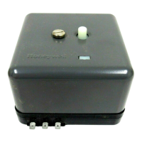
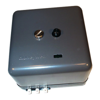
Covers location, weather, subbase mounting, and wiring guidelines.

Flame Detector and Amplifier Setup

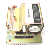
Guidance on installing flame detectors, special considerations, and plug-in amplifiers.

Programmer, Jumper, and System Upgrade Procedures

Steps for installing the programmer, handling covers, setting jumpers, and system upgrades.

Model Replacement Wiring Diagrams

Field wiring diagrams for replacing R4140 models with other types.

Checkout Procedures

Preliminary Inspection and Static Checkout

Initial system checks, checkout summary, and static tests for external devices.

Flame Signal Measurement and Pilot Ignition Tests

Procedure for measuring flame signal and performing pilot ignition checks.

Detector Performance and Safety Shutdown Tests

Tests for detector response to refractory, UV sources, and safety shutdown functions.

Troubleshooting and Service

Troubleshooting Guide and Flame Checks

Troubleshooting precautions, chart, flame relay, and signal checks.

Scheduled Maintenance and Testing

Recommended schedule for periodic inspection, maintenance, and testing of controls.

Related product manuals