63-2565 B.B. 1-00 www.honeywell.com
Home and Building Control Home and Building Control Honeywell Asia Pacific Inc.
Honeywell Inc. Honeywell Limited-Honeywell Limitée Room 3213-3225
Honeywell Plaza 155 Gordon Baker Road Sun Hung Kai Centre
P.O. Box 524 North York, Ontario No. 30 Harbour Road
Minneapolis, MN 55408-0524 M2H 3N7 Wanchai
Hong Kong
Honeywell Latin American Region Honeywell Europe S.A.
480 Sawgrass Corporate Parkway 3 Avenue du Bourget
Suite 200 1140 Brussels
Sunrise FL 33325 Belgium
Printed in U.S.A. on recycled
paper containing at least 10%
post-consumer paper fibers.
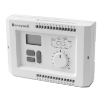
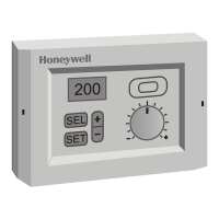
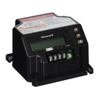
R7426A,B,C,D TEMPERATURE AND UNIVERSAL INPUT CONTROLLERS
NOTES:
— XOFFS = -SOFFS for heating control if Dir/RevO1
is Rev.
— XOFFS = SOFFS for cooling control if Dir/RevO1
is Dir.
— For occupied function, SOFFS = 0.
— OAT
comp
is Reset Effect.
Return Air Offset: RetOffs (P.20)
Parameter RetOffs is available on R7426B,C controllers
only
.
For mixed air damper or energy recovery system control, it
activates
Economizer
mode when On.
NOTE: With the main temperature sensor (I01) installed in
the exhaust air, set RetOffs to 0.
With the main sensor installed in the room and with a constant
offset between room and exhaust air conditions, this offset
value can be adjusted from 0°F to 9°F using RetOffs. This
value is added to the measured room temperature to simulate
exhaust air conditions.
When RetOffs is programmed to Off, or with no OAT sensor
connected,
Economizer
mode is disabled.
RuntimeO1, O2, O3 (P.21,P.22,P.23)
Parameters RuntimeO1,O2,O3 are available on R7426A,B
controllers
only
.
For three-position floating actuator control, the controller
converts the deviation signal to a proportional output pulse.
This pulse drives the actuators based on the Runtime value.
An automatic synchronization function ensures correct
actuator positioning. Synchronization run time is derived by
multiplying Runtime by 1.25.
By selecting pwm mode for output O1 or O3, the pwm output
(suitable for driving electric heat current valves) is controlled
from the heating signal. Interval and total cycle time is set by
the parameter RuntimeO1 or RuntimeO3.
Derivative Decay Time/Amplification: td/vd (P.27/P.28)
P+I+D control adds the derivative function to P+I control to
enhance control behavior. The derivative function opposes
change and is proportional to the rate of change (derivative).
If input I01 deviates from the master setpoint (CTRP1), the
derivative function outputs a corrective action to bring I01
back more quickly than by integral action alone.
Derivative amplification (vd) determines derivative action
effect after a rate of change of I01.
Decay time (td) determines the control output (O1) decay after
derivative action (see Fig. 11).
NOTE: In main and cascade control applications, td and vd
determine the derivative function. In main control
with high/low limits, these parameters determine the
two derivative functions of main and high/low limit
control.
DERIVATIVE AMPLIFICATION AND DECAY TIME P+I+D CONTROL
SETTING GUIDELINES
The proper setting depends on the time constants (such as
Tu), of the system being controlled.
Parameters vd and td can be set using the following:
NOTE: With derivative amplification (vd) set to 1, decay time
(td) should be set at 0.42Tu.
Response time (Tu) in discharge air control normally ranges
from 0.1 to 0.6 minutes. This allows adjustments to decay
time (td) in a range from 2-1/2 to 15 seconds.
td
0.42
T
u
⋅
vd
--------------------
=
 Loading...